Model Components
A PFC model simulates the movement of particles and walls and their physical interaction at pair-wise contacts. We denote each particle as a body to clarify that it is not a point mass, but a rigid body with finite mass and well-defined surface. The PFC model consists of bodies, pieces, and contacts (see Figure 1). There are four types of bodies: balls, clumps, rigid blocks, and walls. Bodies have surface properties that are assigned to the pieces on the body surface. A ball consists of one piece, which is the ball itself, while the pieces of a clump and wall are called pebbles and facets, respectively. A rigid block consists of one piece, which is the rigid block itself. A ball is a rigid unit-thickness disk in 2D and rigid sphere in 3D. A clump is a collection of pebbles that are rigid unit-thickness disks in 2D and rigid spheres in 3D. Clumps model arbitrarily shaped rigid bodies. The pebbles comprising a clump can overlap but contacts do not exist between them; instead, contacts form between the pebbles on the boundary of a clump and the pieces of other bodies. A rigid block is a rigid unit-thickness polygon in 2D and rigid polyhedron in 3D. A wall is a collection of facets that are rigid unit-thickness segments in 2D and rigid triangles in 3D and that form a manifold and orientable surface. Bodies may have surface properties that can be assigned to each piece on the body surface; these surface properties may be used to determine the piece interactions. Bodies exist within the model domain and cannot move outside of this region.
The motion of balls, clumps, and rigid blocks obeys Newton’s laws of motion, but the motion of walls is user-specified; thus, only balls, clumps, and rigid blocks have mass properties (mass, centroid position, and inertia tensor) and loading conditions (the force/moment applied from contacts, a body force arising from gravity, and an externally applied force/moment).
Contact mechanics is embodied in particle-interaction laws that employ a soft-contact approach, for which all deformation occurs at the contacts between the rigid bodies. The mechanical interaction between the surfaces of two bodies occurs at one or more pair-wise mechanical contacts. Contacts are created and deleted during the contact detection step of the cycle sequence based on piece proximity. A contact provides an interface between two pieces. [Contacts are referred to by the types of the two pieces. For example, a contact between a ball and facet is called a ball-facet contact and has a contact type of ball-facet. In the current PFC model, facet-facet contacts are not allowed, thereby giving a total of 9 contact types as shown in Figure 2] The interface consists of a contact plane with location \((\mathbf{x_c})\), normal direction \((\hat{\mathbf{n}}_\mathbf{c})\) and coordinate system \((nst)\). The contact plane is centered within the interaction volume (either gap or overlap) of the two pieces, oriented tangential to the two pieces and rotated to ensure that relative motion of the piece surfaces remains symmetric w.r.t. the contact plane. Each contact stores a force \((\mathbf{F_c})\) and moment \((\mathbf{M_c})\) that act at the contact location in an equal and opposite sense on the pieces of the two bodies [1]. The internal forces/moments are updated by the particle-interaction law, which takes the relative motion and surface properties of the two pieces as input. We refer to the particle-interaction law as a contact model [2].
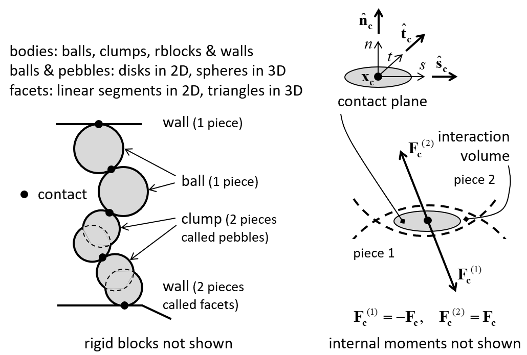
Figure 1: PFC model showing bodies, pieces, and contacts (left) and contact plane with internal force (right).
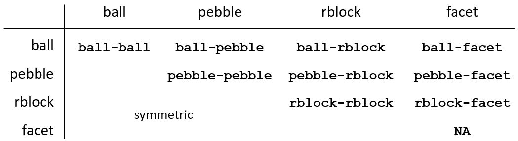
Figure 2: Contact types (nine of them) are based on the types of the two contacting pieces.
A PFC model is created and manipulated by issuing commands. The commands pertinent to each PFC model component are detailed in the section describing this component (i.e., among the sections balls, clumps, rigid blocks, walls, and “Contacts and Contact Models”). Many additional utilities exist to facilitate the modeling process; these are described in the “Common Model Objects” section. The listing of all commands related to PFC model components is available in the PFC Command Summary section. An index of all commands in this documentation (includes FLAC3D and 3DEC commands) is available.
Nearly all aspects of a PFC model are accessible via an internal scripting language called FISH. See the “FISH Scripting Reference” section for an introduction to FISH. Similar to commands, the FISH functions available to access/modify PFC model components are detailed in the corresponding section describing this component. A listing of all FISH functions related to PFC model components can be found in the “Index: PFC FISH Functions” section. All FISH functions in this documentation (includes FLAC3D and 3DEC functions) is provided in the FISH Index as well.
Endnotes
| Was this helpful? ... | Itasca Software © 2024, Itasca | Updated: Apr 04, 2025 |
