MPAC Examples • Verification
Cook’s Membrane: Volumetric Locking and Zone Coupling (MPAC2D)
Problem Statement
Cook’s membrane is widely used as a benchmark for modeling incompressible elasticity (Cook, 1974). The membrane has a trapezoidal shape, as shown in Figure 1, fixed on the left-hand side and modeled with a uniform traction on the right-hand side of 1/16 N/m. The material is modeled as linear elastic with the following properties:
Young’s modulus (\(E\))
70 Pa
Poisson’s ratio (\(\nu\))
0.499 (nearly incompressible)
Density (\(\rho\))
1 kg/m3
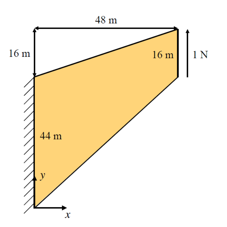
Figure 1: Cook’s membrane showing the basic geometry, dimensions and boundary conditions.
Modelling Procedure
The membrane is first created by defining 44 \(\times\) 44 zones, i.e., each with a height of 1 m on the left-hand boundary. The zones on the left-hand side are then used to import as mpoints using the command below. Note that all constitutive models and properties are imported from the zones. (see mpoint import).
; Import mpoints from selection of zones; including cmodel and properties
[x_split = 40]
mpoint import from-zones range position-x 0 [x_split]
The final discretization is shown below with mpoints on the left-hand portion, and zones on the right-hand side. The background mesh is created using a length (spacing) of 1 m. The background cells are similar in size to the zones, and the nodes to the left of the membrane are all fixed.
Checking the mesh density using the mpoint mesh-density command, the average number of mpoints per background cell is 4.8 which is sufficient for a 2D analysis where the optimal number of mpoints per cell is 4. Of the 1362 active cells, only 247 cells have less than four mpoints.
mpoint mesh-density
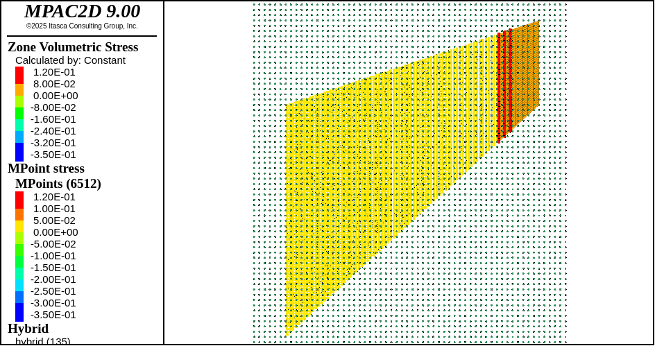
Figure 2: Cook’s membrane showing the background mesh, mpoints and zones.
The zones are coupled to the background mesh by defining hybrid-points (coupled gridpoints) using the command mpoint hybrid-points. All gridpoints within two background cell lengths to the right of the coupling region are defined as hybrid-points.
; Coupling
[ml = mpoint.node.spacing]
zone face group 'coupling' internal range position-x [x_split] [x_split+2*ml]
mpoint hybrid-points range group 'coupling'
The load is applied to the faces of the zones on the right-hand side, and the local damping is set to 0.4 for the background mesh and the zones.
; Apply load to zone face
zone face apply stress-shear [-1.0/16.0] range position-x 48
; Set damping
mpoint node damping local 0.4
zone mechanical damping local 0.4
In MPAC volumetric locking is mitigated using the command mpoint locking-adjustment on.
mpoint locking-adjustment on
The vertical tip displacement is recorded after the model is cycled for 50,000 steps.
Results
The benchmark for the vertical tip displacement is taken as 0.275 m based on the work by Rodriguez et al. (2016) (FEM model with a fine mesh of 6400 elements in total), Bisht et al. (2021) (MPM) and Zhao et al. (2022) (MPM). Note that these authors used a Neo-Hookean (non-linear hyper-elastic) constitutive model, while a standard linear elastic model is used in this study. Although the material properties are chosen so that the membrane’s maximum displacement is relatively small, the non-linear material response might lead to slightly different results.
Not specifying a locking adjustment (the default setting where locking is not mitigated), the predicted tip displacement is accurate. However, the stress distribution is not ideal as shown below where the volumetric stress is plotted. It is clear that the mpoints experience volumetric locking, resulting in a non-smooth stress field. The zones do not experience any significant locking.
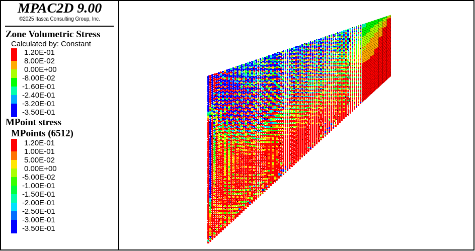
Figure 3: Cook’s membrane showing the volumetric stress for zones and mpoints without locking mitigation and Poisson’s ratio \(\nu\) = 0.499.
Setting mpoint locking-adjustment on, locking is mitigated, and the tip displacement is 0.277 m with a smooth stress distribution as shown below. It is also clear that the stress distribution is continuous across the coupling of zones and mpoints. Note that the stress field for the mpoints and the zones were not smoothed in these plots.
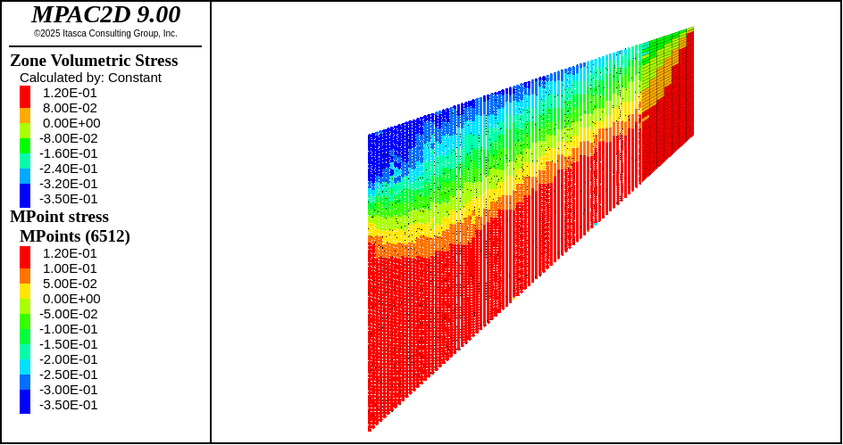
Figure 4: Cook’s membrane showing the volumetric stress for zones and mpoints with locking mitigation and Poisson’s ratio \(\nu\) = 0.499.
Setting Poisson’s ratio to a value more commonly encountered, \(\nu\) = 0.3 without locking mitigation, the stress distribution is smooth as shown below. Thus, for elastic materials, locking mitigation is not needed for lower values of Poisson’s ratio.
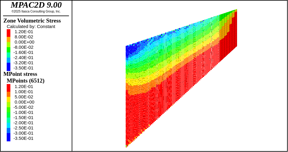
Figure 5: Cook’s membrane showing the volumetric stress for zones and mpoints without locking mitigation and Poisson’s ratio \(\nu\) = 0.3.
References
Bisht, V., Salgado, R. and Prezzi, M., 2021, Simulating penetration problems in incompressible materials using the material point method, Computers and Geotechnics 133, 103593.
Cook, R., 1974, Improved two-dimensional finite element, Journal of the Structural Division 100(9), 1851–1863.
Rodriguez, J., Carbonell, J., Cante, J. and Oliver, J., 2016, The particle finite element method (PFEM) in thermo-mechanical problems, Int. J. Numer.Meth. Engng 107, 733–785.
Zhao, Y., Jiang, C. and Choo, J., 2022, Circumventing volumetric locking in explicit material point methods: A simple, efficient, and general approach, International Journal for NumericalMethods in Engineering (September), 1–27.
break
Data File
CooksMembrane.dat
model new
model domain extent -3 50 -3 70
model large-strain off
; Create zones
zone create quad point 0 (0,0) ...
                 point 1 (48,44) ...
                 point 2 (0,44) ...
                 point 3 (48,60) ...
                 size 44 44
; Set zone material properties/attributes
zone cmodel assign elastic
zone property young 70.0 poisson 0.499 density 1.0
; Create background mesh
mpoint node spacing 1
mpoint node fix velocity range position-x -3 0
; Import mpoints from selection of zones; including cmodel and properties
[x_split = 40]
mpoint import from-zones range position-x 0 [x_split]

mpoint mesh-density

; Coupling
[ml = mpoint.node.spacing]
zone face group 'coupling' internal range position-x [x_split] [x_split+2*ml]
mpoint hybrid-points range group 'coupling'
; Apply load to zone face
zone face apply stress-shear [-1.0/16.0] range position-x 48
; Set damping
mpoint node damping local 0.4
zone mechanical damping local 0.4
; Model settings
mpoint locking-adjustment on
; History of tip-displacement
[gp = gp.near(vector(48,60))]
[gp_id = gp.id(gp)]
zone history name 'Tip-disp' displacement component y gridpointid [gp_id]
; Solve the model
model cycle 50000
; Final tip-displacement
[gp.disp.y(gp)]
; eof
| Was this helpful? ... | Itasca Software © 2024, Itasca | Updated: Nov 23, 2025 |
