Wall-Zone Coupling Scheme
The coupling scheme described below applies to both zone gridpoints and structural element nodes. In the description below, bold variables denote vectors and non-bold variables denote scalars.
PFC walls are created coinciding with zone faces or shell-based structural element surfaces. Walls are composed of edge-connected, triangular faces where vertex velocities and positions can be specified as a function of time. The coupling logic works by taking the contact forces and moments with wall facets and determining an equivalent force system at the facet vertices. These forces are passed to the gridpoints/nodes along with stiffness contributions. In addition, stiffness and force criteria (see the wall-zone update-tolerance and wall-structure update-tolerance commands) are checked to trigger zone/structural element updates. These updates change both geometric parameters and zone/structural element stiffnesses in order to ensure numerical stability. Note that for the coupling to be active during cycling, mechanical computations must be in large strain mode, set via the model largestrain command. The discussion below presents results for situations where zones have triangular faces (note: shell-based structural elements are always triangular). When zone faces are quadrilaterals, they are broken into two triangles. In this situation forces are calculated for the three gridpoints corresponding with the wall facet, not for all four gridpoints of the quadrilateral face. This is in contrast to the situation where 1D structural elements are linked to zones. In that case, weights are calculated based on the force application point to all quadrilateral faces and no effort is made to balance induced moments.
Immediately following the force displacement law where ball-facet and pebble-facet contact forces/moments are calculated, the equivalent forces are sought at the gridpoints and/or nodes of interest. The scheme varies, with similar reasoning, depending on the dimensionality of the code. First the 2D formulation will be presented, followed by the 3D formulation. Note that an alpha version of FLAC in 2D is provided.
2D Coupling Method
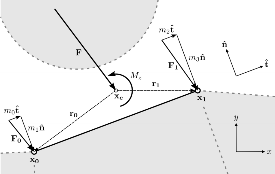
Suppose that a ball is in contact with the linear segment of the wall facet that is wrapping a zone face in 2D as seen below. The equivalent forces at gridpoints \(\textbf{F}_0\) and \(\textbf{F}_1\) are sought given the contact force \(\textbf{F}\) and the moment \(M_z\). The segment orientation, traversing from \(\textbf{x}_0\) to \(\textbf{x}_1\), can be expressed as the unit tangential and normal vectors \(\hat{\textbf{t}} = (t_x,t_y)\) and \(\hat{\textbf{n}} = (-t_y,t_x)\), respectively.
The forces acting at the gridpoints can be rewritten as the sum of scalars in the tangential and normal directions as shown in the equation below.
The goal is to introduce constraints to determine the four unknowns, namely \(m_0\), \(m_1\), \(m_2\), and \(m_3\). The total force applied to the gridpoints must equal the contact force, meaning that:
The forces applied at the gridpoints must also produce the same moment as the contact force for the force system to be equivalent, yielding
where \(\textbf{r}_0 = \textbf{x}_0 - \textbf{x}_c\) and \(\textbf{r}_1 = \textbf{x}_1 - \textbf{x}_c\). In order to solve this underdetermined system of equations (i.e., three equations and four unknowns), an additional constraint must be provided. In particular, suppose that the shear force is distributed to the gridpoints based on distance to the contact point
meaning that \(m_0\) is known. This quantity can be substituted into the equation of total force above giving
and
Multiplying the first equation by \(t_x\) and the second by \(t_y\) and adding them together produces
since \({t_x}^2 + {t_y}^2 = 1\).
Plugging the analytic expressions for \(m_0\) and \(m_2\) into the moment equilibrium equation allows one to solve for \(m_1\) and \(m_3\) for the two cases \(t_y \ne 0\) and \(t_x \ne 0\). For \(t_y \ne 0\),
where \(\Delta x = r_0x - r_1x\) and \(\Delta y = r_0y - r_1y\).
For \(t_x \ne 0\)
Note that, though analytic expressions exist, the determinant of the 3X3 matrix is solved numerically in the code. Otherwise, when switching from one solution to the other, numerical perturbations can occur depending on the numerical criteria for making the switch.
3D Coupling Method
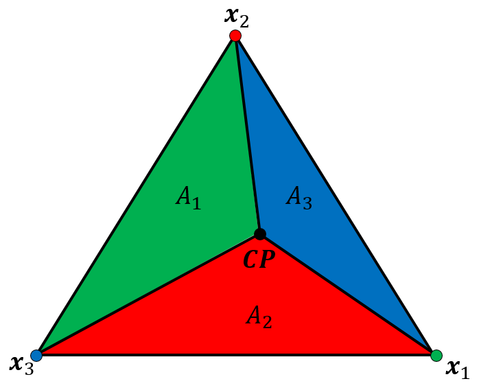
Suppose that a ball is in contact with a triangular wall facet that is wrapping a zone face or a shell-based structural element. \(\textbf{C}\) denotes the position of the contact point and \(\textbf{CP}\) defines the position of the closest point on the wall facet to \(\textbf{C}\). The location of \(\textbf{C}\) is defined in the PFC manual description of the faceted wall logic. The most simplistic method of extrapolating values from \(\textbf{CP}\) to the vertices of the triangle, which coincide with the zone gridpoints or structural element nodes, is through barycentric interpolation/extrapolation. Take the three triangular vertex locations to be \(\textbf{x}_i, i = 1 ... 3\) as shown in the figure below. Define the areas of the three triangles created by connecting the vertices of the triangle with \(\textbf{CP}\) as \(A_i, i = 1 ... 3\), and the total area of the triangle as \(A = \sum_{i=1}^{3} A_i\). In the descriptions that follow, all summations go from \(i=1...3\).

Figure 2: Depiction of barycentric interpolation scheme. The color of a triangle opposite a vertex coincides with the vertex color.
Weighting factors are determined for each vertex by taking the triangle area opposite a vertex divided by the total area of the triangle, yielding \(w_i = \frac{A_i}{A}\). Note that \(\sum w_i = 1\) so that the sum of values extrapolated from \(\textbf{CP}\) to the vertices is equal to the value at \(\textbf{CP}\). When the full computation mode is turned off (see the wall-zone full-computation and wall-structure full-computation commands), contact forces and translational stiffnesses are extrapolated to the gridpoints and nodes via this formulation. For structural element coupling, contact moments result from bonds and the rotational stiffnesses are also extrapolated to the nodes in this manner. Barycentric extrapolation does not ensure that the extrapolated forces and moments are consistent with the contact force/moment in the sense that the total moment at \(\textbf{CP}\) due to both the vertex forces, and potentially the vertex moments, may not be balanced as described below.
Take \(\textbf{r}_i, i = 1...3\) as the vectors pointing from \(\textbf{CP}\) to the respective triangle vertices (i.e., \(\textbf{r}_i = \textbf{x}_i - \textbf{CP}\)). Take the forces applied at each gridpoint or node to be \(\textbf{F}_i, i = 1...3\), the contact force applied at \(\textbf{C}\) to be \(\overline{\textbf{F}}\), and the contact moment due to bonding to be \(\overline{\textbf{M}_b}\). Since the contact point \(\textbf{C}\) and the closest point on the facet, \(\textbf{CP}\), may not be at the same location, the total moment acting on the facet is given by
where \(\times\) is the cross product.
When full computation mode is active, the coupling scheme determines a fully consistent equivalent force system so that
and
Take \(\hat{\mathbf{n}}\) to be the unit vector pointing in the direction of the triangle normal. The force vector along the triangle surface is given by
(13)\[\overline{\textbf{F}}^{shear} = \overline{\textbf{F}} - \overline{\textbf{F}} \cdot \hat{\mathbf{n}}\]
Take
If \(\overline{\textbf{F}}^{shear} = \textbf{0}\), the \(\hat{\mathbf{s}}\) direction is determined by taking the cross product of one of the non-coincident Cartesian axis directions with \(\hat{\mathbf{n}}\).
The equivalent force system is determined in the local axis system where the x-component coincides with the \(\hat{\mathbf{n}}\) direction and the y-component coincides with \(\hat{\mathbf{s}}\) direction. Take \(\textbf{r}_i^{l}\), \(\textbf{F}_i^{l}\), \(\overline{\textbf{F}}^{l}\) and \(\overline{\textbf{M}}^{l}\) to be in this local system and corresponding to \(\textbf{r}_i\), \(\textbf{F}_i\), \(\overline{\textbf{F}}\) and \(\overline{\textbf{M}}\), respectively. As the point \(\mathbf{CP}\) is on the triangle surface, the x-components of each \(\textbf{r}_i^{l}\) are 0, or \(r_{i,x}^{l} = 0\). This simplification allows one to directly determine the x-components of the vertex forces in this local system, \(F_{i,x}^{l}\), via the solution to the simultaneous equations
and
The following three equations remain to be solved with 6 unknowns:
and
Let the y-components of the force be distributed due to the barycentric weighting terms described above, namely \(F_{i,y}^{l} = w_i \overline{F}_y^l\). Thus, the barycentric weighting is applied in the direction of the maximum contact force in the plane of the triangle. The result of this assumption leads to the following two equations with three unknowns:
and
There are infinitely many solutions to this underdetermined system of equations without an additional constraint. The governing equations do not provide a clear decision on the nature of this constraint to find an equivalent system. In this work the additional constraint
is used to provide a particular solution. This constraint is equivalent to stating that, if one were to apply forces at each gridpoint or node in the local z-direction, that the sum of dot products of the vectors pointing from \(\textbf{CP}\) to the triangle vertices in the local system is 0. The resulting forces are subsequently converted into the global axis system and applied to the appropriate zone gridpoints or structural element nodes. In addition, zone/structural element updates are triggered at this time.
Immediately following the zone/structural element equations of motion, the positions/velocities of the wall facet vertices are set according to the corresponding gridpoint/node positions/velocities. The addition of stiffnesses to the gridpoints/nodes is accomplished during the zone/structural element updates directly. When there are rotational stiffnesses present at contacts, these must also be accounted for to ensure stability. An equivalent translational stiffness is determined by taking the magnitude of the rotational stiffness divided by \(\sum \parallel r_i \parallel\).
| Was this helpful? ... | PFC 6.0 © 2019, Itasca | Updated: Nov 19, 2021 |

