
Creating Points and Edges
With the point-edge tool ( ) active, click the desired starting location for an edge in the construction view, then move the mouse to the desired end location, then click again. The second click completes the edge.
To create just a single point, click a location in the construction view, then click it again. The first click “positions” the point, the second “sets” it. In effect, drawing a single point can be thought of as drawing a zero-length edge.
The point-edge tool can connect pre-existing points or split an edge by adding a point onto an edge.
If you start creating an edge and decide you no longer want to create it, the Esc key will cancel the edge creation process.
Intersecting Edges
Zoning will require that edges be formed into blocks. As a result, the point-edge tool has the following rule: one edge cannot be drawn to cross another (see the image below). Any time edges meet, a point must mark the location where they do.
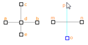
Figure 1: Illustration of valid and invalid techniques for drawing edges
The cross shape on the left is valid, and was created by drawing the horizontal edge from a to b, then drawing the vertical by drawing c to d first, then d to e. Note the process of creating the central point (d) during the making of the vertical also causes the original single horizontal edge (a-b) to be split into two edges (a-d and d-b). The right part of the image shows an invalid attempt to draw a vertical (o-p) that crosses the first horizontal edges (m-n). If you attempt to terminate the vertical at the upper position (p) as shown, an error message will result.
Keyboard Modifiers
- When drawing edges:
- Holding down the Control key provides snap-to-angle functionality. This constrains the angle of drawn edges to 15 degree increments (that is, it “snaps” the angle in fixed increments). The default value is 15 degrees but can be changed in the “Extrusion” panel of the Options Dialog.
- Holding down the Shift key will suppress snap-to-object functionality, which is on by default. Note that when the Shift key is held down, an underlying object will not show a cyan highlight, since it will not be used as the “target” of the next operation.
Curved Edges
The edges created with the Point-Edge tool come in three types: line, curve, and arc. By default, all newly created edges are of the line type. The default setting can be changed in the Extrusion panel of the Options dialog. Edge type is a property of the edge that may be assigned or changed using either the Popup Property Editor or the Control Panel.
The control point tool ( ) is used to refine an edge. To add a control point, select the tool and put the mouse at the point on an edge where a control point is to be inserted. The target edge will highlight in cyan to indicate the control point will “land” on the target edge. Click with the tool to add the point.
An edge of line type will create a straight segment between two points; adding control points will split the line into sub-segments, but each of these will always be straight. An edge of the curve or arc type will be straight if it has no control points. Curve types are cubic splines; arc types are circular. Using one control point on an arc type will create a circular shape between two points. Either arc or curve will accept multiple control points, with quite similar (though not identical) results. There is no calculational or other advantage to using one preferentially to the other.
- Control points may be moved/positioned in the following ways:
- At the moment of inserting (clicking) the point, drag (without releasing the left mouse button) to the desired position and then release the mouse, thus inserting and positioning the control point in one operation.
- With the control point tool () OR the selection tool (
 ) active, left-click-and-drag on an existing control point to move it to a new location.
 - With the point-edge tool() or the blocking tool (
 ) active, right-click-and-drag a control point to a new location.
The Delete key will delete selected control points.
Keyboard Point Creation
Points may be quickly created via keyboard. Pressing any number key, the “-” key, the “@” symbol, or pressing SPACEBAR when nothing is currently selected will show the popup property editor as seen below; the text (other than SPACEBAR) that was used to call the dialog will be entered into the edit field.
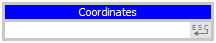
Figure 2: The popup property editor for specifying the coordinates of a point
Entering coordinates in the editor then pressing “Enter” will create a point at the specified position. Pressing ESC cancels the editor and no changes are made.
Fish Input
The editor will accept a FISH variable as input as well. If the variable specified has not yet been defined, a second dialog will follow that requests an acceptable definition of the FISH variable (as below).
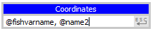
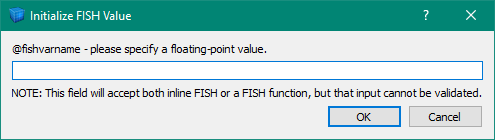
FISH variable names should start with the “@” character. One or two variables may be supplied. If one is supplied, it represents a coordinate pair; two variables separated by a comma represent an individual coordinate in each variable.
Using the Right Mouse Button: Selecting, Moving, Deleting and Merging Points
While the point-edge tool or control point tool is active, selection functions of the left mouse button transfer to the right button.
You can right-click points, control points, edges and blocks to select them. Holding the Control key down while you right-click will let you add and remove objects from a multiple selection. You can also use a selection rectangle to select a range of objects.
With the control-point tool, right-clicking an edge will make the context menu appear. You can ignore the menu and select more edges, or use the menu to change the edge type.
The right mouse button also lets you drag selected objects to new positions.
After you’ve made a selection, pressing the Delete key will cause the selection to be deleted.
You can drag one point to another point to merge the two points. Holding down the Shift key while you drag a point will stop the point from merging with another point.
The Information control set shows the merge tolerance (that is, how close two points must be to produce a merge) in model coordinates. As the view magnification increases, this value decreases.
| Was this helpful? ... | PFC 6.0 © 2019, Itasca | Updated: Nov 19, 2021 |