Single Zone Loading-Unloading Test with MohrT Model
Note
To view this project in FLAC3D, use the menu command . Choose “ConstitutiveModels/ SingleZoneMohrCoulombTensionCrack” and select “SingleZoneMohrCoulombTensionCrack.f3dprj” to load. The project’s main data file is shown at the end of this example.
This example compares the MohrT Model and the traditional Mohr-Coulomb model with quasi-static loading-unloading of a single zone, subjected to unidirectional/bidirectional strain.
Quasi-Static Loading-Unloading of a Single Zone — Unidirectional Strain
One zone with unit dimension is subjected to unidirectional strain, including reversal of extension and compression. The material parameters are summarized in Table 1. The zone has an initial isotropic stress of -1000 Pa. The strains in the y-direction are zero. The velocities in the planes of y = 0 and z = 0 are fixed at zero. The velocity in the plane of x = 1 is 1×10⁻⁸ m/s (extension). The zone is strained for 500 steps; then, the velocity in the plane of x = 1 is changed to -1×10⁻⁸ m/s (compression) and the zone is strained for 800 steps. The applied strain history is summarized in Table 2. The data file is appended as “SingleZoneMohrCoulombTensionCrack-1d.f3dat”.
| Material Parameter | Value |
|---|---|
| \(K\) (Pa) | 2.5e8 |
| \(G\) (Pa) | 1.5e8 |
| \(\phi\) | 30 |
| \(\psi\) | 10 |
| \(c\) (Pa) | 1000 |
| \(\sigma^t\) (Pa) | 200 |
| Loading Direction | Strain Range |
|---|---|
| Extension | x-direction: 0 to 5e-6 |
| Composition | x-direction: 5e-6 to -3e-6 |
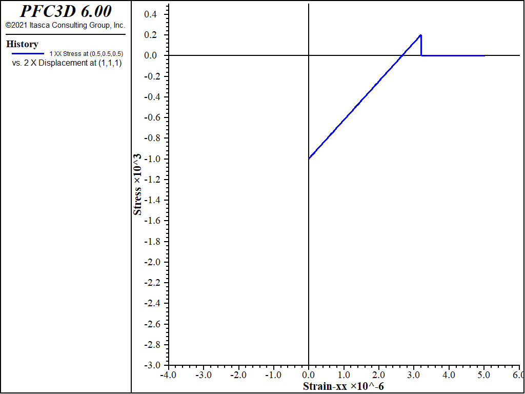
Figure 1 shows the stress versus strain in the zone in the x-direction during the zone extension. As the strain is changing from zero to 5×10⁻⁶, the stress is changing from the initial -1000 Pa to the tension limit of 200 Pa and then suddenly drops to zero because the crack occurs when the stress reaches the tension limit. The stress in the loading direction remains zero during the further extensional strain. When querying the zone parameters, the number of cracks (number-cracks) is 1, and the unit normal direction for crack number 1 is (1,0,0).
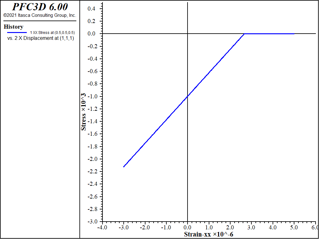
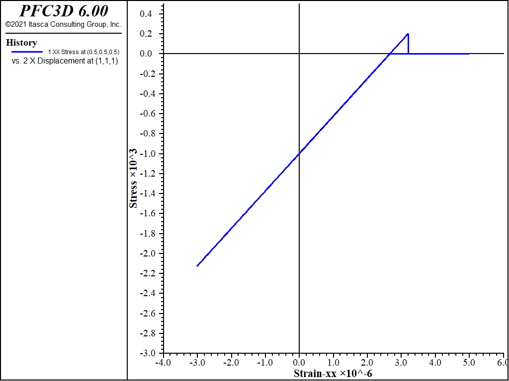
Figure 2 shows the stress versus strain in the zone in the x-direction during the compression phase of the test. As expected, the compressive stress is not developed until the crack is closed. After the crack is closed, the stress-strain path then is along the reversed direction of loading. When querying the zone parameters, the number of cracks is still 1, and crack number 1 (unit normal direction) is still (1,0,0). The overlapped loading and unloading paths in Figure 3 show that the model tensile cracking is fully reversible and that compressive stresses do not develop until the crack is closed. Figure 3 shows the complete stress versus strain path of loading and unloading.
It is interesting to compare the complete stress-strain path with the one (shown in Figure 4) generated when the model is changed to a Mohr-Coulomb model but with the same material parameters as in Table 1. Two major differences between the MohrT and Mohr models are:
- when one principal stress reaches the tension limit, it remains at the tension limit with the Mohr-Coulomb model while it suddenly drops to zero with the MohrT model; and
- after reversal of the strain rate (from extension to compression), the compressive stress is immediately generated with the Mohr-Coulomb model while it is developed only after the crack is completely closed with the MohrT model.
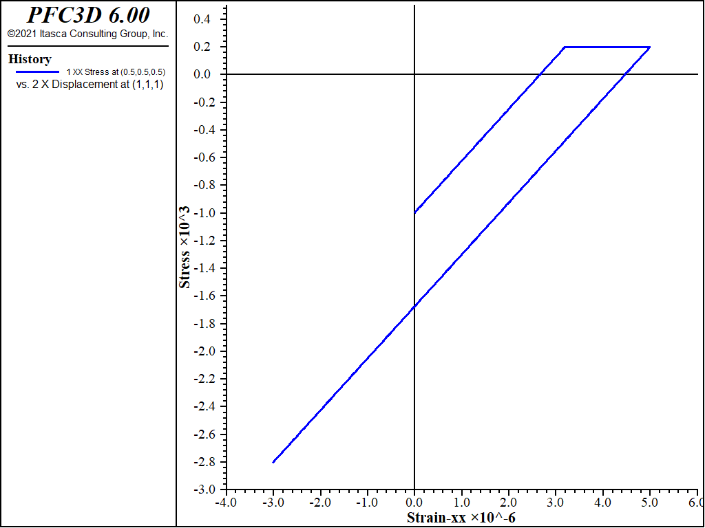
Figure 4: Stress versus strain in the x-direction during the complete strain history using the traditional Mohr-Coulomb Model.
Quasi-Static Loading-Unloading of a Single Zone — Bidirectional Strain
One zone with unit dimension is subjected to bidirectional strain including reversal of extension and compression. The same material parameters summarized in Table 1 are used in this example. The zone has an initial isotropic stress of -1000 Pa. The velocities in the plane of x = 0 and y = 0 are fixed to be zero. The velocity in the plane of x = 1 is 1×10⁻⁸ m/s and the velocity in the plane of y = 1 is 2×10⁻⁸ m/s (i.e., extension in both directions). The zone is strained for 500 steps; then, the velocity in the plane of x = 1 is changed to -1×10⁻⁸ m/s and the velocity in the plane of y = 1 is changed to -2×10⁻⁸ m/s (i.e., compression in both directions) and the zone is strained 800 steps. The applied strain history is summarized in Table 3. The data file is appended as “SingleZoneMohrCoulombTensionCrack-2d.f3dat”.
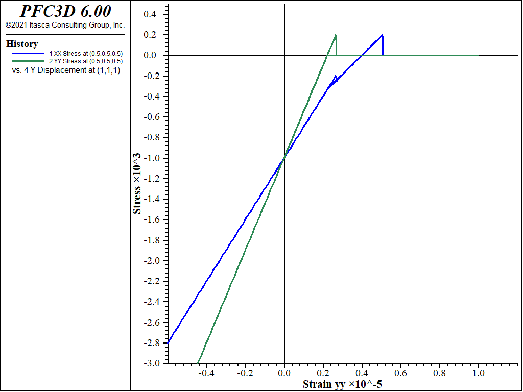
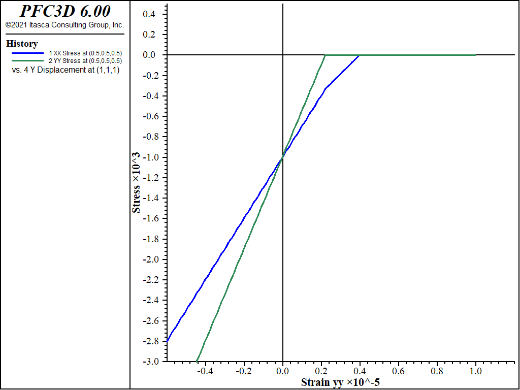
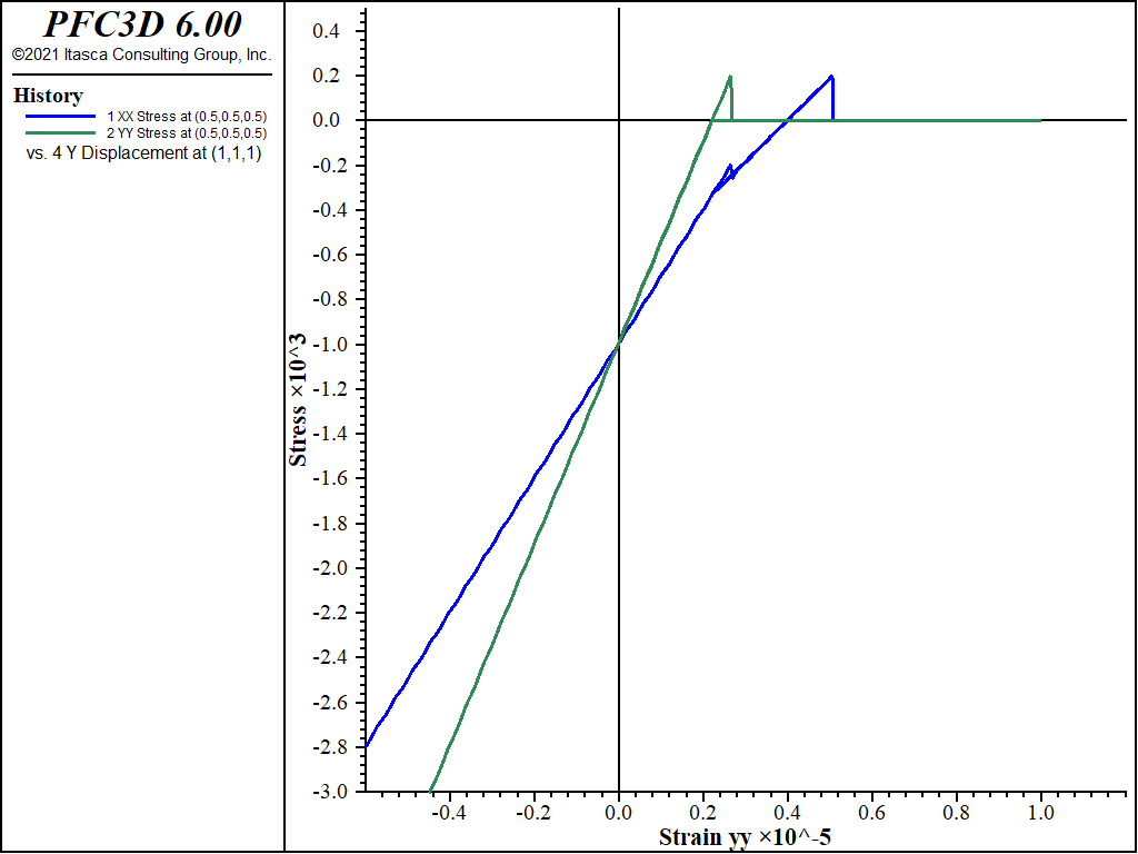
Figure 5 shows the stresses \(\sigma_{xx}\) and \(\sigma_{yy}\) versus strain during loading in the extension direction. As the strain in the y-direction is changing from zero to 1×10⁻⁵, the stress \(\sigma_{yy}\) is changing from the initial -1000 Pa to the tension limit of 200 Pa and then suddenly drops to zero because the crack occurs when the stress reaches the tension limit. The stress \(\sigma_{yy}\) remains zero during further extensional strain. After the step when \(\sigma_{yy}\) drops to zero, the number of cracks (number-cracks) in the zone is set to one, and the unit normal direction for crack number 1 is (0,1,0).
It is interesting to find that the \(\sigma_{xx}\) stress also has a sudden change when the first crack is created; this is due to the Mohr-type failure model being based on the maximum and minimum principal stresses, and when \(\sigma_{yy}\), which is the maximum principal stress in this example, suddenly changes from 200 Pa to zero, it has an impact on stress in other principal stresses.
The second crack with a normal direction (1,0,0) is developed when the \(\sigma_{xx}\) stress reaches 200 Pa. At the end of the loading path, the number of cracks (number-cracks) is two. Figure 6 shows stress–strain behavior during reversed (compression) strain following the extensional strain. The crack in the x-plane is closed first, and the crack closure in the y-plane occurs subsequently. As illustrated in Figure 7, which shows the complete stress versus strain path of loading and unloading, after the cracks are closed, the stress–strain path during compression follows the path during extension.
A comparison showing the complete stress versus strain path of loading and unloading is plotted in Figure 8 when the model is changed to the traditional Mohr-Coulomb model. This example also confirms the reversibility of the tensile cracking in the MohrT model.
| Loading Direction | Strain Range |
|---|---|
| Extension | x-direction: 0 to 5e-5 |
| y-direction: 0 to 1e-4 | |
| Composition | x-direction: 5e-5 to -3e-5 |
| y-direction: 1e-4 to -6e-4 |
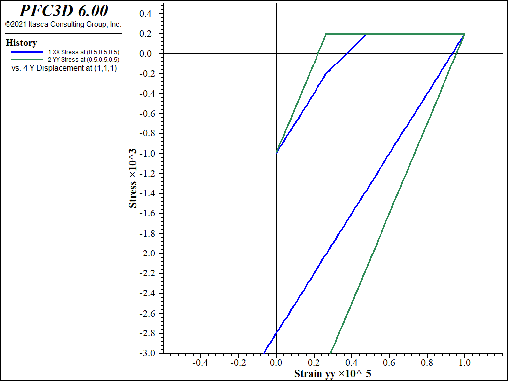
Figure 8: Stress versus strain in the y-direction during the complete strain history using the traditional Mohr-Coulomb Model.
Data Files
SingleZoneMohrCoulombTensionCrack-1d.f3dat
model new
model largestrain off
zone create brick size 1 1 1
zone face skin
zone cmodel assign mohr-coulomb-tension
zone property bulk 2.5e8 shear 1.5e8 cohesion 1e3 fri 30 dilation 10 tension 200
;
zone initialize stress xx -1000 yy -1000 zz -1000
zone face apply stress-yy -1000 range group 'North'  or 'South'
zone face apply stress-zz -1000 range group 'Bottom' or 'Top'
;
history interval 1
zone history stress-xx      position (0.5,0.5,0.5)
zone history displacement-x position (1.0,1.0,1.0)
;
zone face apply velocity-x   0.0 range group 'West'
zone face apply velocity-x  1e-8 range group 'East'
model step 500
zone face apply velocity-x -1e-8 range group 'East'
model step 800
model save 'mohrt1d'
return
SingleZoneMohrCoulombTensionCrack-2d.f3dat
model new
model largestrain off
zone create brick size 1 1 1
zone face skin
zone cmodel mohr-coulomb-tension
zone property bulk 2.5e8 shear 1.5e8 cohesion 1e3 fri 30 dilation 10 tension 200
;
zone initialize stress xx -1000 yy -1000 zz -1000
zone face apply stress-zz -1000 range group 'Bottom' or 'Top'
;
history interval 1
zone history stress-xx position (0.5,0.5,0.5)
zone history stress-yy position (0.5,0.5,0.5)
zone history displacement-x position (1.0,1.0,1.0)
zone history displacement-y position (1.0,1.0,1.0)
;
zone face apply velocity-x   0.0 range group 'West'
zone face apply velocity-y   0.0 range group 'South'
zone face apply velocity-x  1e-8 range group 'East'
zone face apply velocity-y  2e-8 range group 'North'
model step 500
zone face apply velocity-x -1e-8 range group 'East'
zone face apply velocity-y -2e-8 range group 'North'
model step 800
model save 'mohrt2d'
return
| Was this helpful? ... | PFC 6.0 © 2019, Itasca | Updated: Nov 19, 2021 |

