Soil Nailing
Problem Statement
Note
To view this project in FLAC3D, use the menu command . Choose “Structure/Cable/SoilNailing” and select “SoilNailing.f3prj” to load. The main data files used are shown at the end of this example. The remaining data files can be found in the project.
This example demonstrates the ability of cable elements to simulate support provided by materials such as soil nails in the construction of reinforced embankments. In this example, three soil nails are installed at different levels in a vertical embankment. Two conditions are examined: (1) only cohesive resistance is assumed between the nails and the soil; and (2) both cohesive and frictional resistance are included.
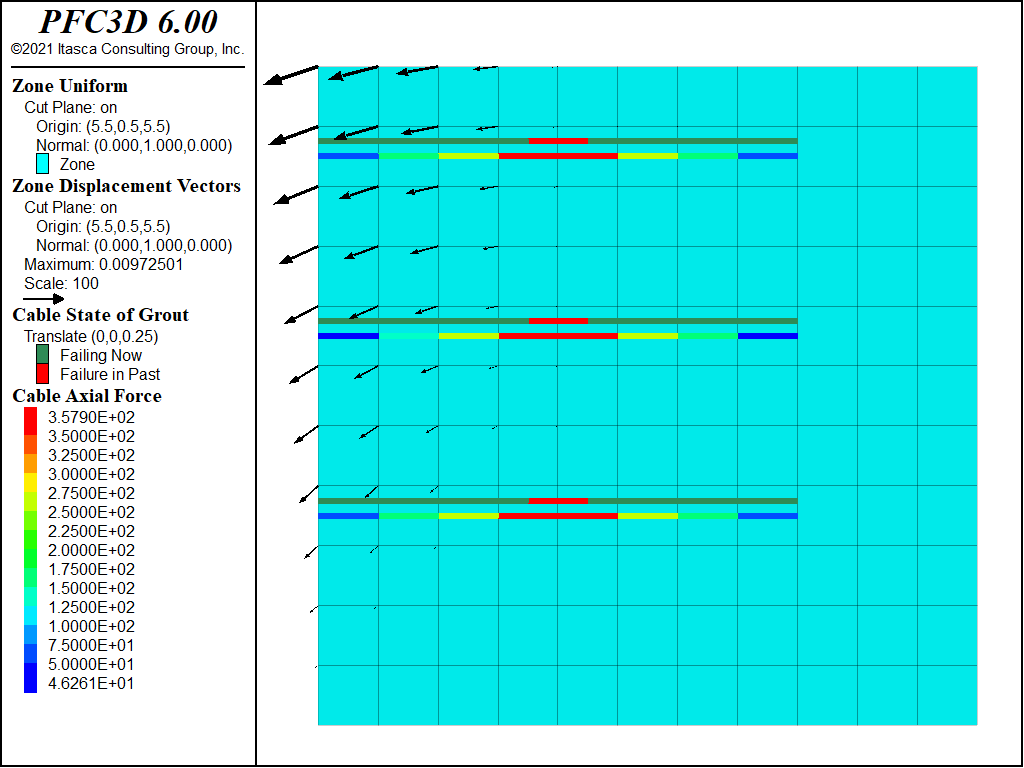
In the first case, the soil nails are not sufficient to support the embankment. Figure 1 shows the axial forces in the cables, and indicates that the slip condition has been reached in the grout for all nodes.
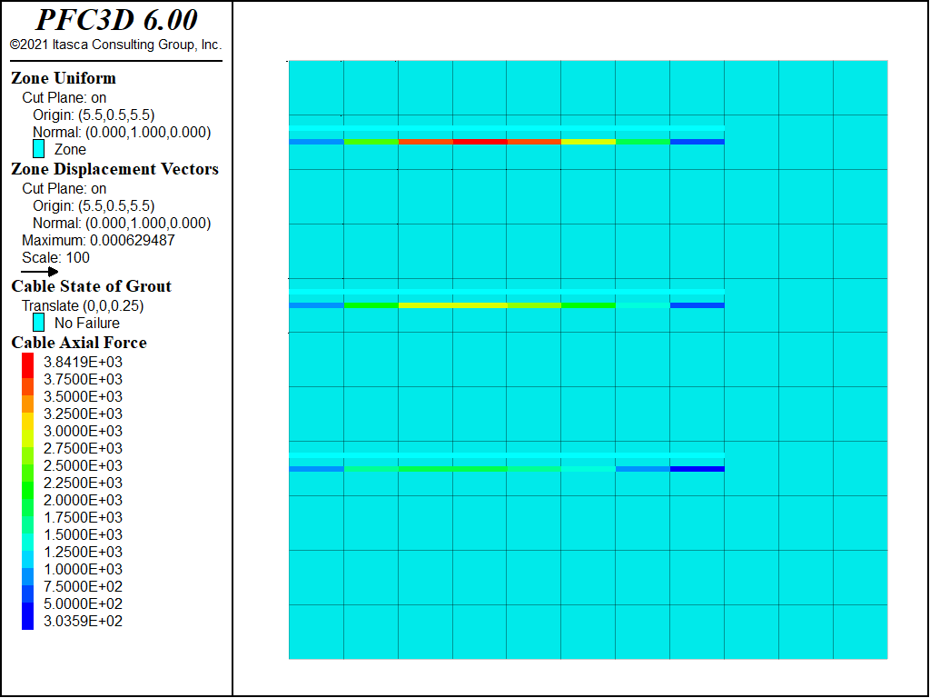
In the second case, by including a frictional resistance at the nail/soil interface of 25°, the nails are now sufficient to stabilize the embankment. Figure 2 plots the axial forces in the cables for this case. Note that significantly higher axial forces can now develop as a result of the frictional resistance.

Figure 1: Axial forces in nails with only cohesive strength at soil/nail interface (the embankment is collapsing).

Figure 2: Axial forces in nails with both frictional and cohesive strength at soil/nail interface (the embankment is stable).
Data File
SoilNailing.f3dat
model new
model largestrain off
model title "Soil nailing (using cables)"
; Create zones
zone create brick size 11 1 11
zone face skin ; Name model boundaries
; Assign constitutive model and properties
zone cmodel assign mohr-coulomb
zone property bulk 5e9 shear 1e9 cohesion 4e4 friction 30 density 2000
; Boundary conditions
zone face apply velocity-normal 0 range group 'East' or 'West'
zone face apply velocity-normal 0 range group 'North' or 'South'
zone face apply velocity (0,0,0) range group 'Bottom'
; initial conditions
model gravity 10
zone initialize-stresses ratio 0.6,0.4
; Solve to initial equilibrium (should be instant)
model solve ratio-local 1e-4
; Release boundary condition on left
zone face apply-remove range group 'West'
; Create cables, and assign properties
struct cable create by-ray (0,0.5,3.5) (1,0,0) 8 segments=8
struct cable create by-ray (0,0.5,6.5) (1,0,0) 8 segments=8
struct cable create by-ray (0,0.5,9.5) (1,0,0) 8 segments=8
struct cable property cross-sectional-area=5.02e-3 young=200e9 yield-tension=1e10 grout-stiffness=7e6 grout-cohesion=1e2
model save 'Start'
; Cycle to equilibrium - we expect to fail so limit cycles as well
model solve ratio-local 1e-4 cycles 5000
model save 'LowFriction'
;
; Re-run with higher friction
model restore 'Start'
struct cable property grout-perimeter=0.314 grout-friction=25
model solve ratio-local 1e-4
model save 'HighFriction'
| Was this helpful? ... | PFC 6.0 © 2019, Itasca | Updated: Nov 19, 2021 |
