
Object Properties
For a general description of how to edit properties, see Object Properties in General.
Starting Point
The starting point, at the bottom-left corner, can have its depth and group name edited in the Popup Property Editor or the Object Properties control set.
Subsequent Points
These points can be selected either one at a time or in groups. When selected one at a time, the Depth property can be edited as well as Group name. When more than one point is selected, only the Group name can be edited.
With nothing selected, you can press the space bar to show the Popup Property Editor and then enter the coordinate for a new point, even if the new point is beyond the end of the current extrusion.
You can use the mouse pointer to drag points to new positions.
Edges
One edge is shown for each stage of the extrusion. When you select an edge, its length, number of zones, ratio and group name can be edited either in the control panel or the Popup Property Editor.
When you change the number of zones or the ratio, the new zoning will be represented by the vertical lines for each stage of the extrusion.
Valid values for ratio range from 0 to infinity. The default value is 1. In practice, values should probably be kept in the range from 0.5 to 2.
Extrusion Axis
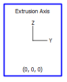
Figure 1: The Extrusion Axis control
By default, an extrusion has an origin at 0,0,0 in model coordinates, and will extrude along the y-axis in the positive direction. These settings can be changed. To do so, select the extrusion axis control by clicking it with the select tool (![]() ). The orientation and position of the extrusion may now be edited either through the Control Panel or via the Popup Property Editor. If the latter is used, a window like the one shown below will appear; the same properties appear in the Control Panel.
). The orientation and position of the extrusion may now be edited either through the Control Panel or via the Popup Property Editor. If the latter is used, a window like the one shown below will appear; the same properties appear in the Control Panel.
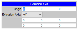
Altering the origin can be done by entering a new x, y, or z coordinate(s), respectively, on the “Origin” line. Changing the extrusion orientation in model space involves selecting one of six basic axis directions (positive or negative x, y, or z). With one of these selected, the position of the origin and the selected direction are sufficient to orient the extrusion.
There is a final option in the “Extrusion Axis” selector for orienting the extrusion: the option “Extrude, X.” When this option is selected, it is necessary to specify two additional values below the selector. The first is labeled “Extrude”, and it defines a unit vector which articulates the direction of extrusion. The second value is labeled “X,” and is used to provide 3D orientation by defining a plane that is formed by itself and the “Extrude” unit vector. With these two defined, an “Extrude, Y” unit vector that is perpendicular to the “Extrude, X” plane is implied; with it an “Extrude Plane X-Extrude Plane Y” plane is defined by FLAC3D. The model is now oriented so that this plane is coincident with the plane on which the construction view sits (the plane holding the “face” of the extrusion). Finally, when a mesh is generated the extrusion direction will be perpendicular to the “Extrude Plane X-Extrude Plane Y” plane, even though the initially supplied “Extrude” unit vector may not be. This adjustment is made automatically when the extrusion is performed.
| Was this helpful? ... | PFC © 2021, Itasca | Updated: Feb 25, 2024 |