Automatic Calculation of a Stable Pit Slope Angle
Problem Statement
Note
To view this project in FLAC3D, use the menu command . Choose “TheoryAndBackground/FactorOfSafety/ BenchExtrusion” and select “BenchExtrusion.prj” to load. The project’s main data files are shown at the end of this example.
A pit slope is excavated in strong rock that contains an 8 m thick vertical band of weak rock. The slope is composed of two 20 m high benches with a 10 m wide berm. Both benches are initially inclined at 60° to the horizontal. Figure 1 shows the initial slope configuration and the location of the weak rock within the strong rock.
The strengths of the strong rock and weak rock are prescribed by a Mohr-Coulomb material model. The strong rock has a cohesion of 15 kPa and a friction angle of 40°, and the weak rock has a cohesion of 7 kPa and friction angle of 120°. Both rock types are assigned a zero tensile strength, a mass density of 2000 kg/m3, a bulk modulus of 10 GPa, and shear modulus of 3 GPa.
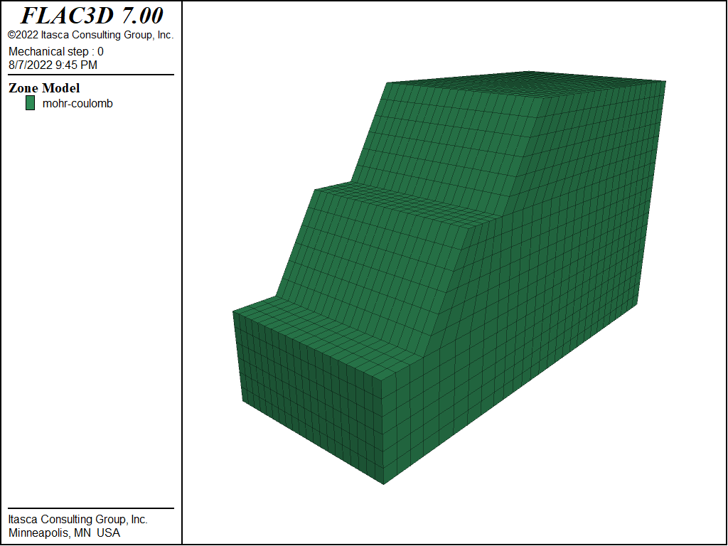
Figure 1: Benched slope in rock with a weak vertical band.
A factor of safety calculation performed for these slope conditions indicates that the slope is unstable. A factor of 0.81 is calculated, and the failure (as shown in Figure 2) is primarily through the weak rock in the upper bench.
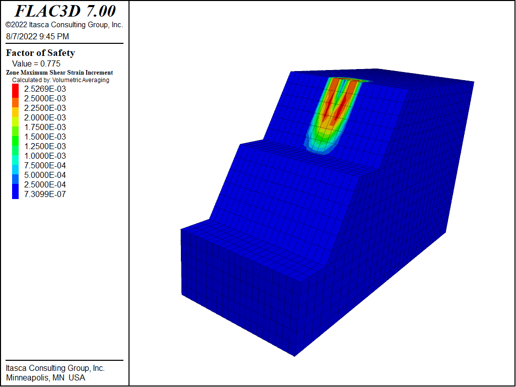
Figure 2: Factor of safety and failure surface (shown by shear strain contours) for slope with benches inclined at 60°.
The purpose of this exercise is to determine the slope angle for the upper and lower benches that produces a stable slope condition with a factor of safety of 1.2. This analysis is performed automatically by adjusting the slope angle in increments until a factor of 1.2 is reached. The model is created using the Extrusion pane in FLAC3D, and a FISH function is used to adjust the slope angle automatically in order to calculate a safety factor for each slope angle. A series of calculations is performed until the factor reaches 1.2.
Figure 3 shows the slope boundary that is sketched first in the construction view of the Extrusion pane. The model width at the base is 100 m, and the model height is 60 m. Additional edges are added to the sketch to divide the slope shape into quadrilateral blocks in order to create a structured grid for this model. See Figure 4.
The zoning is defined in the construction view by specifying a model extent of 30 zones in the Autozone dialog. The blocks in the construction view are all given the group name “strongrock”.
Selected gridpoints are also assigned group names. These gridpoints can then be moved to correspond to the change in slope angle that is performed in the FISH function. The gridpoint at the front of the berm above the lower bench is assigned the group name “pt1”. The gridpoint at the back of the berm and the two gridpoints below this gridpoint are assigned the group name “pt2”. (This assignment is shown in Figure 5.) The gridpoint at the top of the upper bench is assigned group name “pt3”.
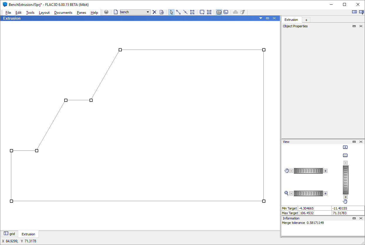
Figure 3: Benched slope boundary sketch in Extrusion pane.
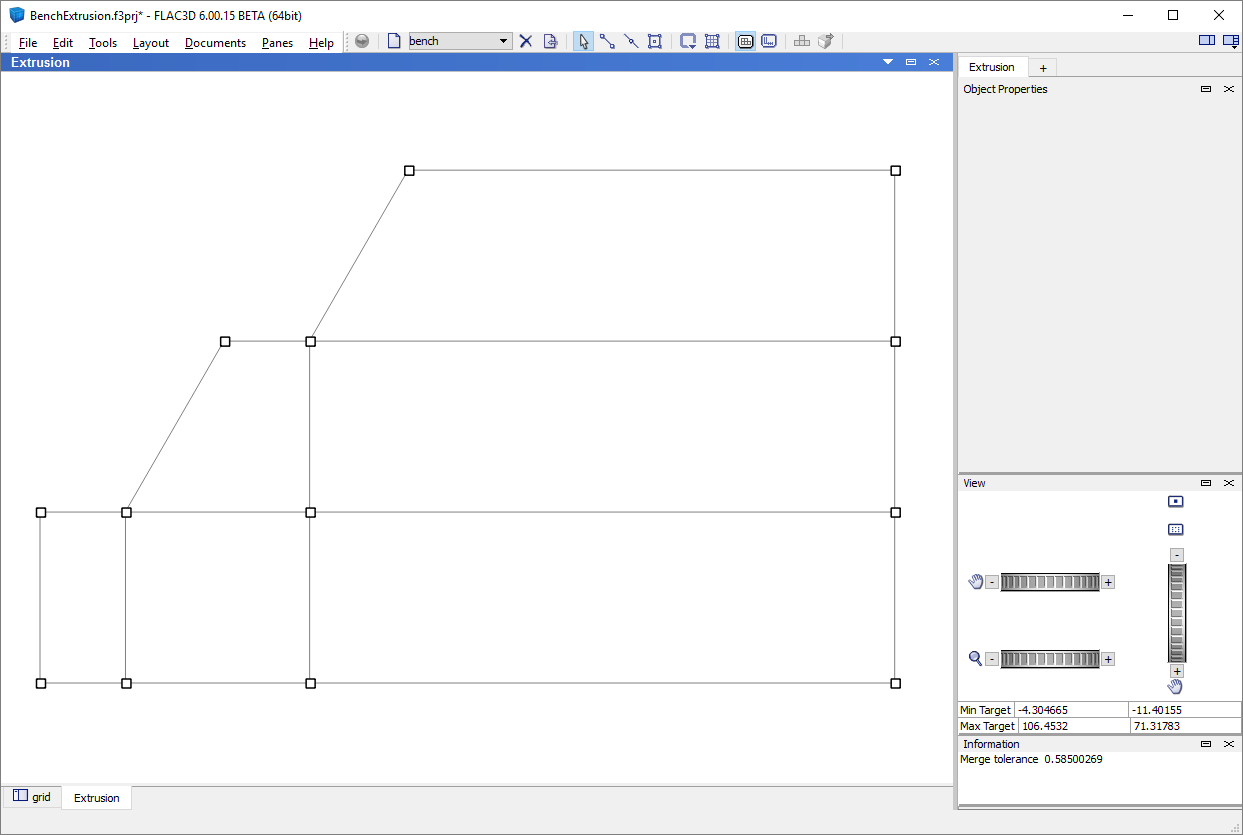
Figure 4: Additional edges to divide the slope shape into blocks.
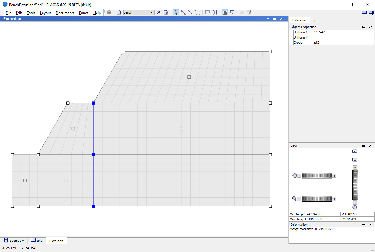
Figure 5: Assignment of group name “pt2” to selected gridpoints in the construction view.
The model depth is prescribed in the extrusion view to be 40 m. The extent of the 8 m wide weak rock is also set, and the zones within this region are given the group name “weakrock”. See Figure 6.
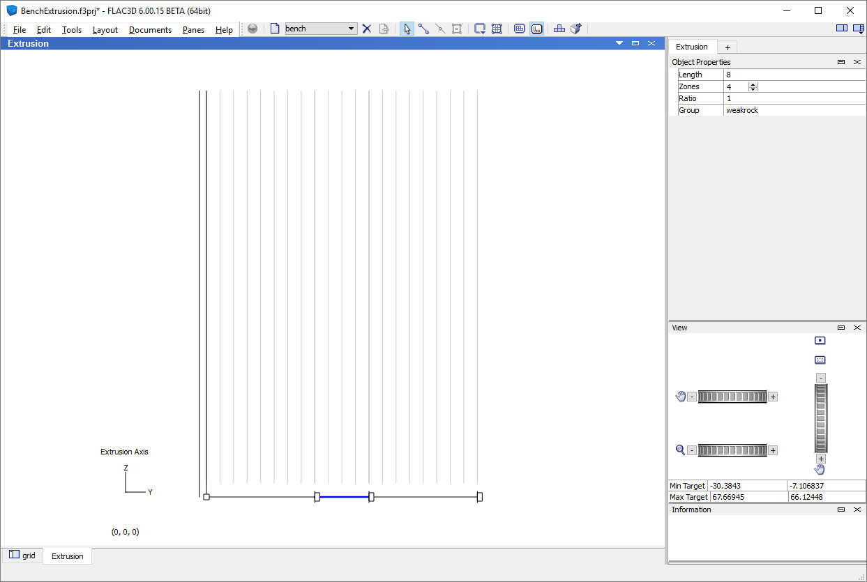
Figure 6: Assignment of group name “weakrock” to zones in the extrusion view.
The extruded model is shown in Figure 7. The mesh in this model is relatively coarse for this illustrative example. The zoning can easily be changed by returning to the Extrusion pane. The input record for this extrusion model is saved from the State Record pane in FLAC3D. The record is named “benchextude.dat”.
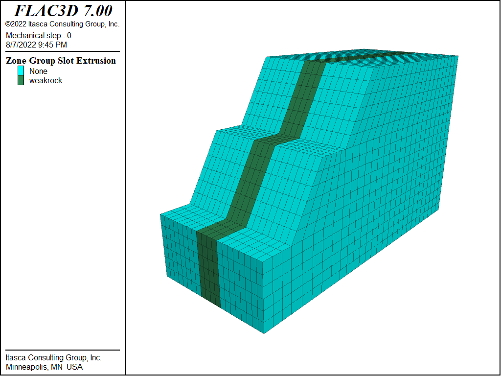
Figure 7: FLAC3D model of a benched slope in rock with a weak vertical band.
A FISH function named benchAdjust in file “benchAdjust.dat” is used to move the gridpoints with group names “pt1”, “pt2”, and “pt3” as the slope angle of the benches is reduced from 60°. At each angle reduction, the extrude points in the model are scanned and the points belonging to those groups have their x-positions adjusted.
The factor of safety is calculated for each change in slope angle. A new grid is created
each time the angle is reduced (using the zone generate from-extruder command),
material properties and boundary conditions are assigned, and a factor of safety
calculation is performed. The commands to create the model for each angle are contained in “benchFOS.dat”.
A factor of safety calculation cannot be initiated from inside a FISH command/end_command statement, because the command restores an initial model state and that state includes FISH. To work around this restriction, FISH is used to create a data file that calculates the factor of safety for each slope angle separately and stores the result in a table.
A total of 11 factor of safety calculations are performed as the slope angle is reduced from 60° to 35°. A table plot of factor of safety values versus slope angle can be displayed during the calculations to monitor the effect of slope angle on safety factor. A plot of the table at the completion of the calculations is shown in Figure 8. From the table, the critical slope (the slope when the factor of safety is 1.0) is approximately 43.5°.
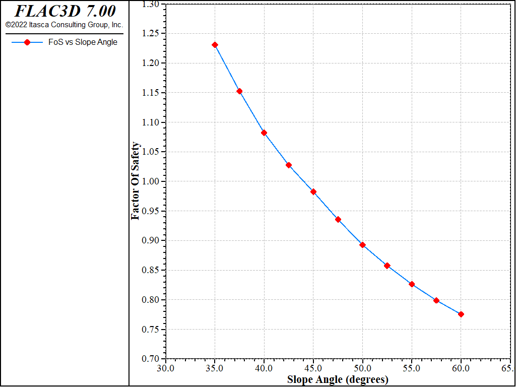
Figure 8: Factor of safety versus slope angle.
The factor of safety is 1.23 at the final inclination of 35°. The failure surface is also confined to the upper bench for this slope geometry, as shown in Figure 9. The table plot in Figure 8 indicates that a factor of 1.2 is reached at a slope angle of 36°.
The FISH function in “benchAdjust.dat” could easily be extended to allow for the adjustment of the upper- and lower-bench slope angles independently and the adjustment of the bench width. Additional runs can then be made to evaluate the effect of variation in these variables on safety factor. (Note that the model boundary is not changed in this illustrative exercise, which limits the range of reduction of the slope angle.)
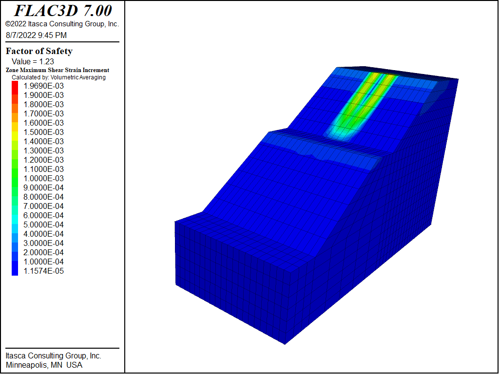
Figure 9: Factor of safety and failure surface for slope with benches inclined at 35°.
Data Files
enchExtrusion.dat
model new
; Created in 2D extruder and exported from state pane
program call 'geometry' suppress
program call 'benchAdjust' suppress ; FISH function to modify slope
model large-strain off
; This FISH function creates a data file to calculate the FOS
; for a range of angles
fish define createDataFile(startang,endang,increment)
    local test = list
    loop local angle (startang,endang,increment)
        test('end','end') =           list.seq('; Angle '+string(angle), ...
                                     '[benchAdjust('+string(angle)+')]', ...
                                   'program call \'benchFOS\' suppress', ...
                         'model factor-of-safety ratio-local 1e-3 ... ', ...
             'filename \'BenchSlope'+string(angle)+'\' ; '+string(angle), ...
               'table \'fos\' insert ('+string(angle)+',[global.fos])' )
    endloop
    file.all('benchrun.dat','text') = test
end
[createDataFile(35,60,2.5)]
program call 'benchrun'
table 'fos' export 'fos-angle' truncate
program system delete 'benchrun.dat'
benchAdjust.dat
;   translate gridpoints as a function of slope angle change
fish define benchAdjust(theta)
    ; Calculate new point position
    local xa = 10 + 20 / math.tan(theta*math.degrad)
    local xb = xa + 10
    local xc = xb + 20 / math.tan(theta*math.degrad)
    ; Update x positions of points marked pt1, pt2, and pt3
    local allpts = list(extrude.point.list(extrude.set.find('bench')))
    local pts1 = allpts(extrude.point.isgroup(::allpts,'pt1'))
    local pts2 = allpts(extrude.point.isgroup(::allpts,'pt2'))
    local pts3 = allpts(extrude.point.isgroup(::allpts,'pt3'))
    extrude.point.pos(::pts1)->x = xa
    extrude.point.pos(::pts2)->x = xb
    extrude.point.pos(::pts3)->x = xc
end
[benchAdjust(35)]
benchFOS.dat
;-------------------------------------------------------------
; Runs a single FOS calculation based on current extruder data
;-------------------------------------------------------------
; Clear away all old zones
zone delete
; Generate zones from extruder data
zone generate from-extruder
; Assign constitutive model and properties
zone cmodel assign mohr-coulomb
zone property density 2000 bulk 1e10 shear 3e9
zone property cohesion 15000 friction 40
zone property cohesion 7000 friction 20 range group 'weakrock'
; Assign boundary conditions
zone face apply velocity-normal 0 range union position-x 0 position-x 100
zone face apply velocity-normal 0 range union position-y 0 position-y 40
zone face apply velocity (0,0,0) range position-z 0
model gravity 10
| Was this helpful? ... | FLAC3D © 2019, Itasca | Updated: Feb 25, 2024 |