FLAC2D for FLAC 8.1 Users
Note
Tables to convert FLAC commands and FISH to equivalent commands and FISH in FLAC2D are provided here: Mapping Commands from Old to New FLAC2D Syntax and Mapping FISH from Old to New FLAC2D Syntax.
FLAC2D was developed to provide a consistent experience for users of FLAC2D and FLAC3D. The necessarily means that FLAC2D 9.0 represents a significant change from FLAC 8.1 (and older). Although the calculation cycle is the same (finite volume discretization with an explicit solver) and most of the FLAC functionality is reproduced in FLAC2D, the way that the user interacts with the program is quite different.
ij space
The most significant difference is that FLAC2D does not require a structured grid. Gridpoints and zones are not identified by their i,*j* coordinates. Instead, they are identified by IDs (see 2). Also, because FLAC2D does not use an i,*j* space, it is possible to create an ustructured mesh as shown in 2. This makes it easier to construct grids without having to form 4-sided shapes with a lot of attach conditions.
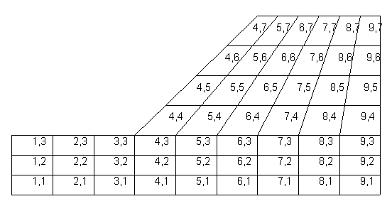
Figure 1: A FLAC model showing i,j coordinates of zones
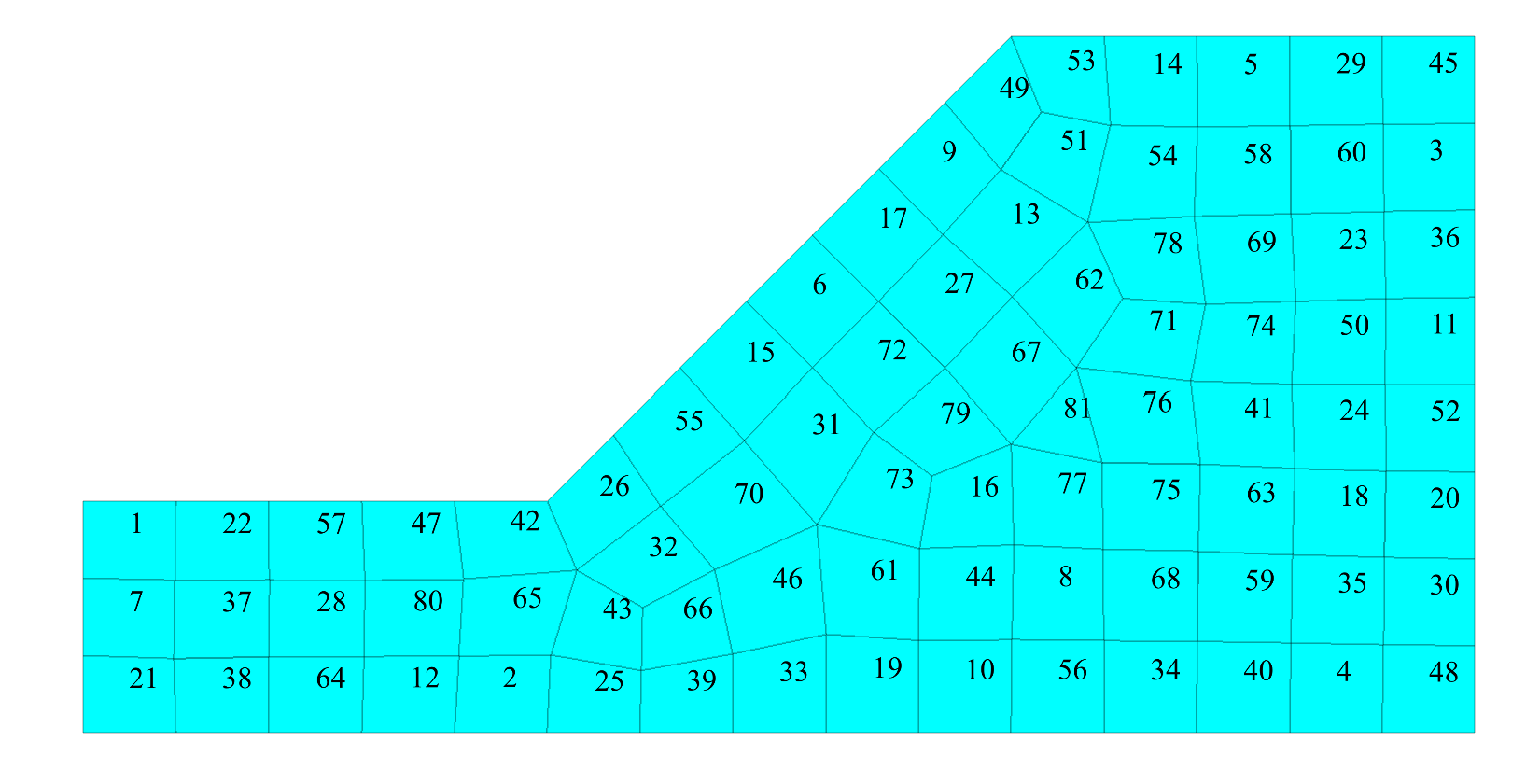
Figure 2: A FLAC2D model showing zone IDs.
Ranges
In FLAC, zones and gridpoints are identified by their i,*j* coordinates. So, for example, to fix the gridpoints on the left side of a model, you may give a command like:
fix x i=1
In FLAC2D, you must use the keyword range when identifying things. Since there is no i,*j*, things are commonly identified with coordinates or group names. A possible equivalent to the above command in FLAC2D would be:
zone gridpoint fix velocity-x range position-x=0
Specifying a mohr-coulomb material model for a group of zones in FLAC2D might look like this:
zone model mohr-coulomb range group ‘sand’
General differences between command syntax in FLAC and FLAC2D are described in Command and FISH Syntax below.
FISH
The lack of an i,*j* space also requires a different method for identifying zones and gridpoints in FISH. A loop through all gridpoints in FLAC might look like this:
loop i (1,igp)
  loop j (1,jgp)
    ; print x coordinate
    ii = out(x(i,j))
  end-loop
end-loop
The same loop in FLAC2D would look like this:
loop foreach gp gp.list
  io.out(gp.pos.x(gp))
end-loop
All gridpoints are stored in a list and are easily looped through by using foreach. The gridpoint is then identified by the user-defined variable gp rather than i and j. More details about FISH differences are given in the next section.
Boundary Conditions
An important difference between FLAC 8.1 and FLAC2D is the application of stress or pore pressure boundary conditions. In FLAC 8.1 the value of applied stress or pore pressure is given at the start of the selected boundary, and the gradient is the change in stress or pore pressure over the entire length of the selected boundary. In FLAC2D, the value specified is always the value at the (0,0) coordinate. The gradient is always the change in stress or pore pressure per unit length along the boundary. Consider a 10x10 m square model with the bottom, left corner at (0,0). If the water table is at the surface and we assume units of Pa for stress, the command to apply pore pressures on the left side might look like this in FLAC
apply pp 0.0 var 0.0 98100 from 1,11 to 1,1
or
apply pp 98100.0 var 0.0 -98100 from 1,1 to 1,11
depending on which way you draw your boundary.
In FLAC2D, the command will always be:
zone face apply pore-pressure 98100 var 0.0 -9810 range position-x 0
Command and FISH Syntax
All commands in FLAC2D attempt to conform to the standard pattern of NOUN - VERB - OPTION - MODIFIERS – RANGE. This was done to provide clarity as to what object is being acted on, and also to enable coupling between programs (e.g. zone gridpoint fix is different than ball fix).
Commands have keywords using a new hyphenated syntax that allows the full command to be documented and listed for ease of understanding, but still allows abbreviation for those who do not want to type the entire word(s). For example, zone initialize stress-xx could be written zone ini str-xx.
Similarly, a new FISH intrinsic naming convention has also been implemented. The type of thing being queried or changed is followed by a . and then the quantity. For example, zone.model or gp.disp. This greatly increases the clarity of function names and allows the editor to automatically highlight both correct and incorrect intrinsic names as you type.
Many new types have also been added to FISH, including Boolean, Tensor, Matrix, List, or Map. Multithreaded FISH is also possible (see Operators: Writing Functions for Multiple Threads).
FISH intrinsics are provided for all quantities in FLAC2D. It is no longer necessary to directly query memory in an array to get some quantities. So, for example, to get shear displacement on a joint:
sjdisp = fmem(pa+$kidasd)  ; FLAC

sjdisp = interface.node.disp.shear(pa)  ; FLAC2D
One final note: in FLAC2D, properties are assigned directly to objects (zones, interfaces, structural elements). There is no indirect assignment as in FLAC where properties are assigned to a number, and then a material number is assigned to an object. For example:
struct prop 1001 e 2e11 area 0.006 I 2e-4
struct beam prop 1001
becomes
structure beam property young 2e11 cross-sectional-area 0.006 moi 2e-4
Tables to convert FLAC commands and FISH to equivalent commands and FISH in FLAC2D are provided here: Mapping Commands from Old to New FLAC2D Syntax and Mapping FISH from Old to New FLAC2D Syntax.
Model Building
FLAC2D provides a Sketch Pane (Sketch (formerly Extrude)) and Model Pane (The Model Pane), which are similar to the Geometry Builder and Virtual grid editor in FLAC. The Sketch Pane allows you to import dxfs or other figures, draw lines and shapes, assign groups and specify zoning densities. An example is shown below.
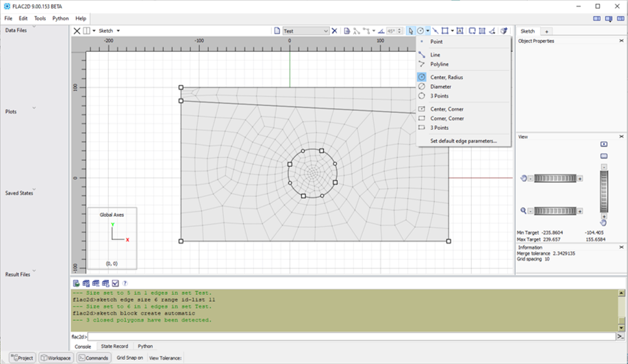
Figure 3: The FLAC2D Sketch Pane.
Once zones are created from the Sketch Pane, the Model Pane allows for interactive assigning of groups, specifying constitutive models and material properties, as well as creating surface structural elements or interfaces (joints) on selected edges. An example is shown below.
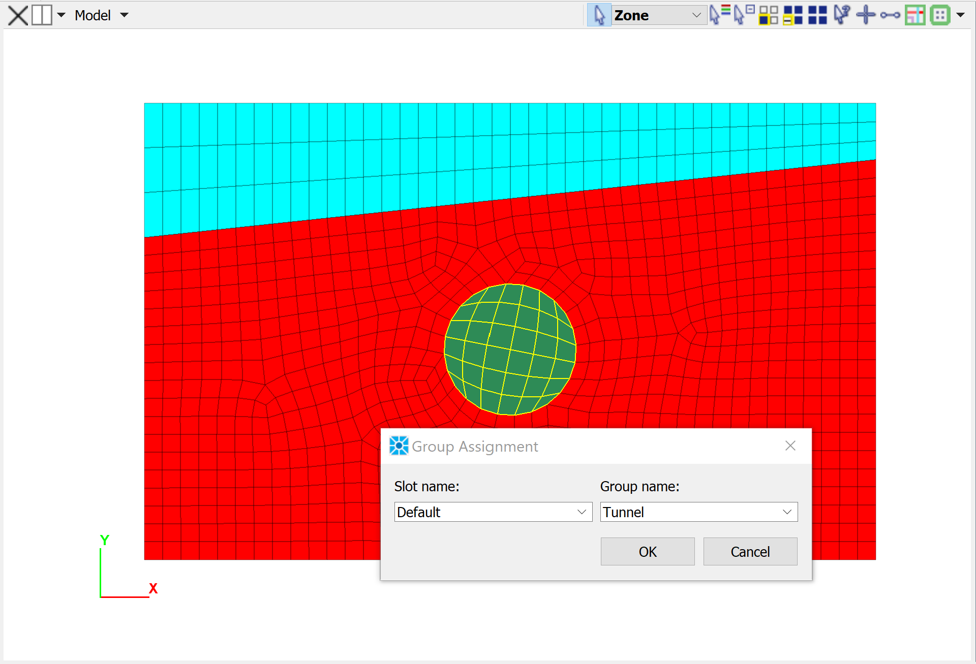
Figure 4: The FLAC2D Model Pane.
If you prefer using commands to build model grids, several ‘primitive’ shapes are provided and can be created and attached together (link to primitive based grids in |flac2d|). It is not possible in FLAC2D to draw lines and force the grid to conform to those lines as in FLAC (e.g. gen line).
Structural elements can be created in FLAC2D by:
Drawing edges in the Sketch Pane and turning them into SELs using the
structure cable import from-sketchcommand (for example).Importing a dxf and using the
struct cable import from-geometrycommand (for example).Giving commands with coordinates (e.g.
struct cable create by-line)Surface elements like liners can be created interactively in the model pane by selecting faces and adding liner elements to the faces.
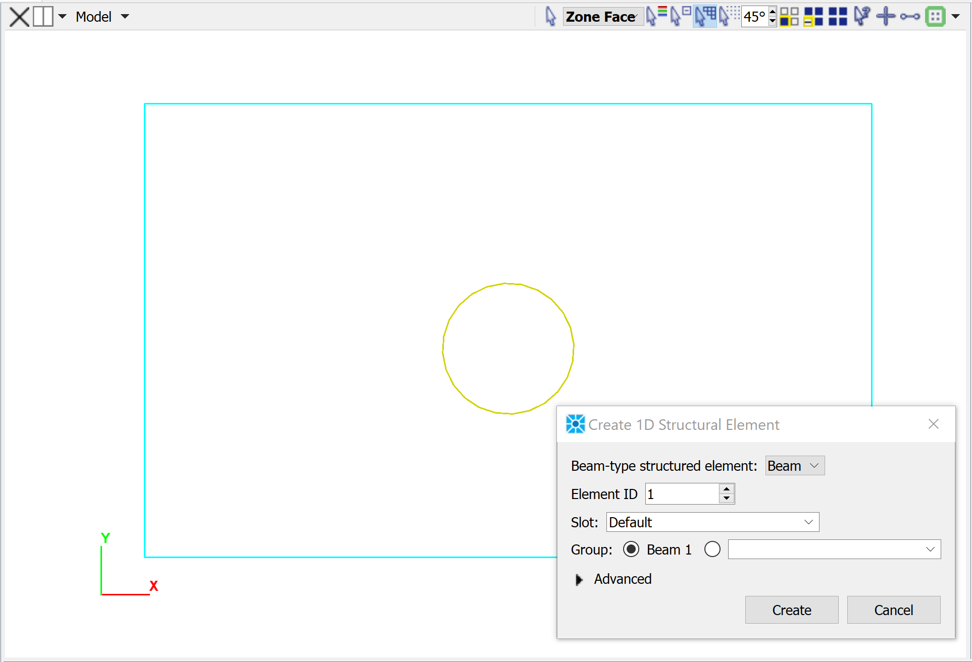
Figure 5: Selected edges (gold color) and dialog to assign beam elements to those edges.
Specifying initial and boundary conditions graphically is not yet possible in FLAC2D, and commands must be used. The ability to assign group names to faces and zones in the Model Pane makes it relatively easy to specify initial and boundary conditions to groups of faces or zones.
Exporting FLAC models to FLAC2D
If you have a complicated model geometry that you have created in FLAC, this can be exported as a grid file that can then be imported into FLAC2D. In FLAC, go to and select Export to |flac2d| (see below). You can then open the model in FLAC2D by going to .
If gridpoints are not aligned across boundaries, you will probably want to give the command zone attach by-face after importing.
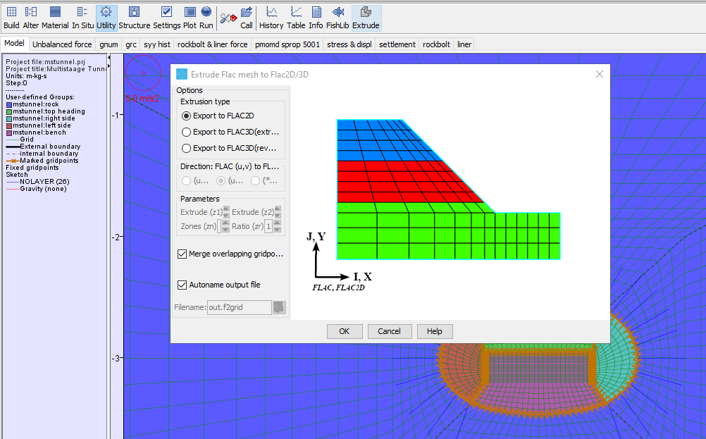
Figure 6: Exporting a grid from FLAC
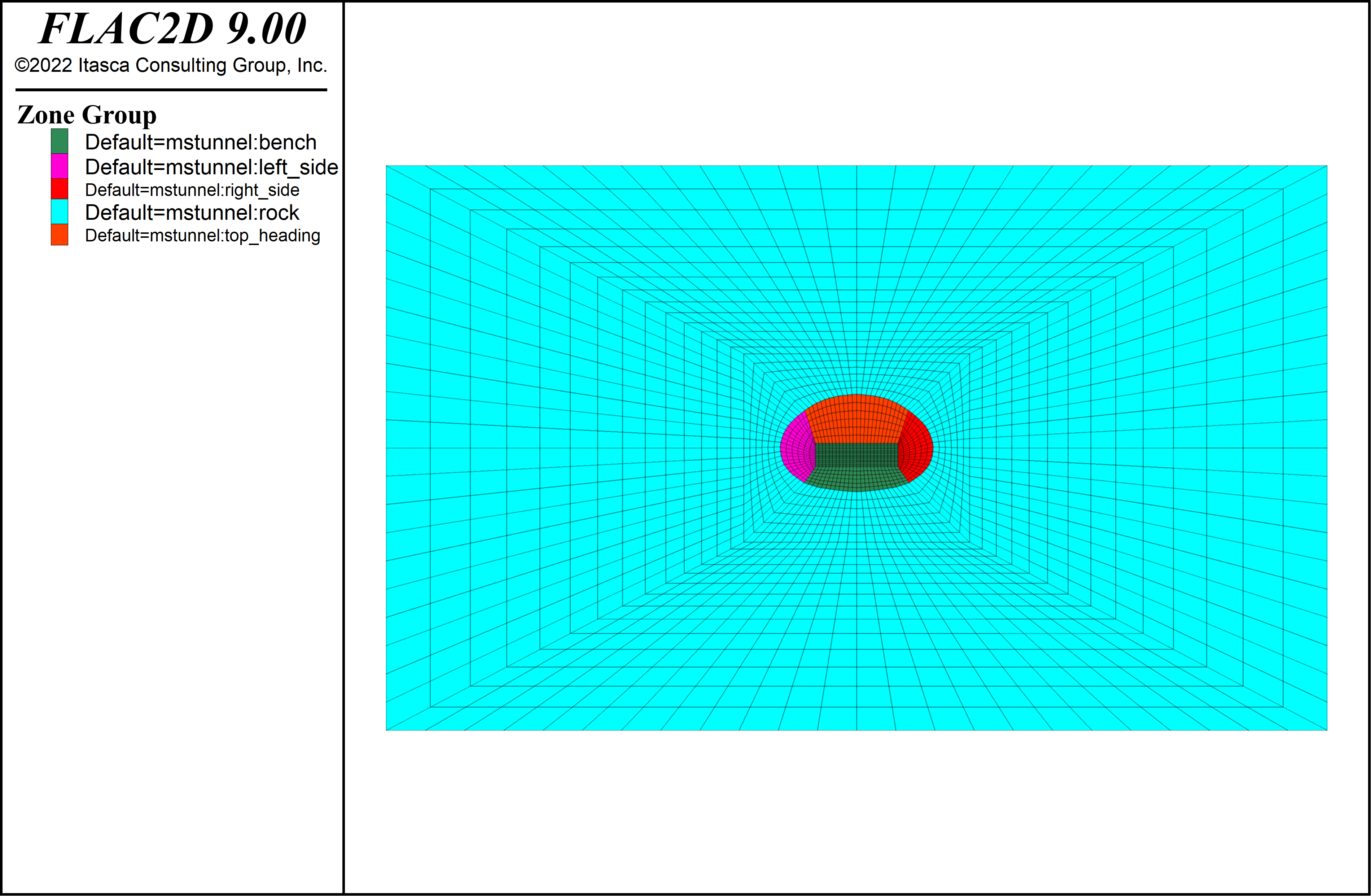
Figure 7: The imported grid in FLAC2D.
It is also possible to export geometries from the FLAC model builder as Sketch commands that can be read by FLAC2D. More here plus example.
Plotting and Visualization
Generating plots in FLAC2D is similar to FLAC. You need to create a new plot and then add specific plot items to it (e.g. zones, vectors, structural elements). One difference is that there is not a long list of possible plot items to choose from. Instead you just choose the thing to be plotted (zones, for example) and then specify a label (e.g. groups) or a contour (e.g. displacements).
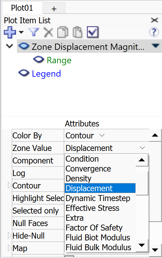
The other difference is that the user has much more control over the colors, scales, fonts, legends, etc for the plots. Outputting of plots is also simple and can be done by right-clicking and selecting a format and resolution.
There is no built-in movie maker in FLAC2D. Instead, functionality is provided to easily enable dumping of plot files at regular intervals (say, every 100 steps). To set this up, go to . It is then easy to use any movie making software (e.g. Video Editor that comes with Windows) to create a movie from the frames.
Miscellaneous
rockbolt in FLAC 8.1 are piles in FLAC2D with the command structure pile property rockbolt-flag on.
FLAC Functionality not in FLAC2D
Not all capabilities in FLAC 8.1 are available in FLAC2D 9. For this reason, Itasca will continue to support FLAC until one year after version 10 of FLAC2D is released. The following functionality is currently not available:
Infinite elastic boundaries
FISH constitutive models
Support elements
Automatic Rezoning. Although this can be done to some extent with FISH see example here.
Two-phase flow. Although air-fluid systems with different permeability-saturation functions and saturation-suction functions can be simulated as described here.
| Was this helpful? ... | Itasca Software © 2024, Itasca | Updated: Nov 12, 2025 |
