Examples • Example Applications
Pile-Supported Highway Embankment
Problem Statement
Note
This project reproduces Example 14 from FLAC 8.1. The project file for this example is available to be viewed/run in FLAC2D.[2] The project’s main data file is shown at the end of this example.
End-bearing piles can be used to support highway embankments constructed over soft foundation materials. This method of support can reduce the potential for excessive deformations and failure during the undrained stage of construction, when excess pore pressures are induced in the foundation materials by the embankment loading.
This example presents a FLAC2D analysis of the initial (undrained) construction stage for a highway embankment built over soft, saturated foundation clay and muck, using timber piles to support the embankment [1]. The piles extend through the soft materials and into underlying silty sands. The embankment includes foamed concrete engineered fill as part of the embankment materials. The lightweight foamed concrete is placed in lifts of approximately 0.6 m thickness. The first lift is placed over a wire mesh directly in contact with the top of the timber piles. Earth fill and pavement material are placed as cover over the foamed concrete. The analysis also includes a traffic surcharge of 11,500 Pa (240 psf). Figure 1 shows a section view of the embankment and foundation materials. The groundwater surface is at the top of the foundation materials.
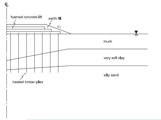
Figure 1: Half-section view of foamed concrete embankment on timber piles.
The properties assumed for the foundation and embankment materials are listed in Table 1 and Table 2. The FLAC2D simulation is an undrained analysis using the groundwater configuration mode. Consequently, the drained modulus and strength properties and the dry mass densities are input for this calculation mode, because the effect of water is incorporated in the FLAC2D calculation.
Property |
muck |
very soft clay |
silty sand |
|---|---|---|---|
Porosity (%) |
90 |
80 |
30 |
Dry density (kg/m3) |
231 |
582 |
1620 |
Drained Young’s modulus (MPa) |
0.3 |
0.5 |
15 |
Drained Poisson’s ratio |
0.49 |
0.45 |
0.3 |
Drained cohesion (Pa) |
3500 |
5000 |
0 |
Drained friction angle (degrees) |
0 |
0 |
32 |
Horizontal permeability (m/day) |
0.003 |
0.0003 |
2.4 |
Vertical permeability (m/day) |
0.001 |
0.0001 |
0.8 |
Property |
foamed concrete |
earth fill |
|---|---|---|
Porosity (%) |
30 |
30 |
Dry density (kg/m3) |
640 |
1920 |
Drained Young’s modulus (MPa) |
600 |
10 |
Drained Poisson’s ratio |
0.15 |
0.3 |
Drained cohesion (Pa) |
50000 |
2400 |
Drained friction angle (degrees) |
0 |
30 |
Horizontal permeability (m/day) |
1.2 |
1.2 |
Vertical permeability (m/day) |
0.4 |
0.4 |
Treated timber piles are located on a 2.5 m by 2.5 m rectangular spacing beneath the embankment materials. The length of each pile is 12.8 m (42 ft), and the average pile diameter is 0.3048 m (12 in). The properties of the timber piles are listed later in Table 3.
Modeling Procedure
This analysis is performed as a parametric study to compare the deformation of an unsupported embankment to that of a pile-supported embankment. In both cases, first determine the initial equilibrium state of the saturated foundation soils. Then, for the unsupported case, add the embankment materials and monitor the vertical displacement along the foundation surface directly beneath the embankment. For the pile-supported case, install the timber piles and then add the layers of embankment materials while monitoring the vertical displacements in the same locations as those for the unsupported case.
Model Geometry
The model takes advantage of half symmetry and is created with Sketch by following these steps:
Create a new Sketch.
Draw a box from 0,0 (top left) to 80,-40 (bottom right).
- For the embankment, draw a polyline through the following points.
0,0
3,0
11.75,3
20.75,0
- For the embankment, draw a polyline through the following points.
- The soil layers are defined by the following lines.
0,-12
20,-10.5
80,-10.5and
0,-9
20,-5
80,-5
- The soil layers are defined by the following lines.
- The embankment consists of 4 layers of foamed concrete overlain by earth fill. To define the earth fill layer, draw the following polyline.
0,2.5
11,2.5
19,0
- The embankment consists of 4 layers of foamed concrete overlain by earth fill. To define the earth fill layer, draw the following polyline.
Now draw horizontal lines from the left side to the edge of the earth fill at `y`=0.7, `y`=1.3, and `y`=1.9. It can be easiest to do this by drawing the lines past the edge of the fill and then deleting the dangling points. The top-left part of the the model should appear as shown below.
Set the zone length to 1 for all zones.
Select all of the horizontal lines that make up the embankment and set the number of zones for these edges to 20.
Select all of the vertical lines on the left side of the embankment and set the number of zones to 2.
Mesh all polygons and generate the zones.
Model Properties
In the model pane, label the groups as shown:
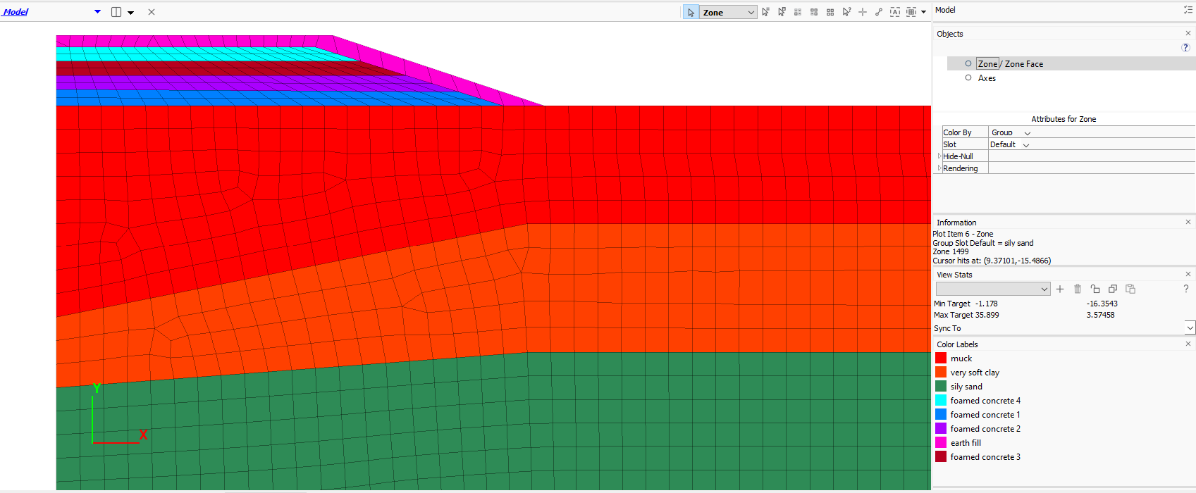
Assign the Mohr-Coulomb constitutive model to all zones. Then assign the properties to the three soil layers as shown in Table 1. Assign the properties to the embankment layers as they are added.
Finally, automatically assign face groups to the model. Make sure to uncheck the box to assign group names inside the model and check the box to ignore existing group names.
Save the project and the state.
Initial State
Fluid properties, initial stresses, and boundary conditions are set up with the commands in the data file c initial.dat. Note that the anisotropic fluid model is used and different hydraulic conductivities are assigned in the horizontal and vertical directions for each layer. Here hydraulic-conductivity``is used, which is the rate of fluid flow through the material in units of m/s, as opposed to ``permeability, which is the hydraulic conductivity divided by the unit weight of water (in FLAC2D).
The embankment layers are initially set to constitutive model null. The water table is assumed to be at the surface. The water bulk modulus is initially set the unrealistically low value of 10,000 to speed convergence to steady state.
In this model, the initial stresses are not automatically calculated from gravity and density, but are instead calculated using a table or measured values and a FISH function that installs the stresses for each zone by interpolating from the table.
Also, because large deformations during the embankment construction are anticipated, the calculations are peformed in large-strain mode. The pore pressures after solving for the initial state are shown in Figure 4.
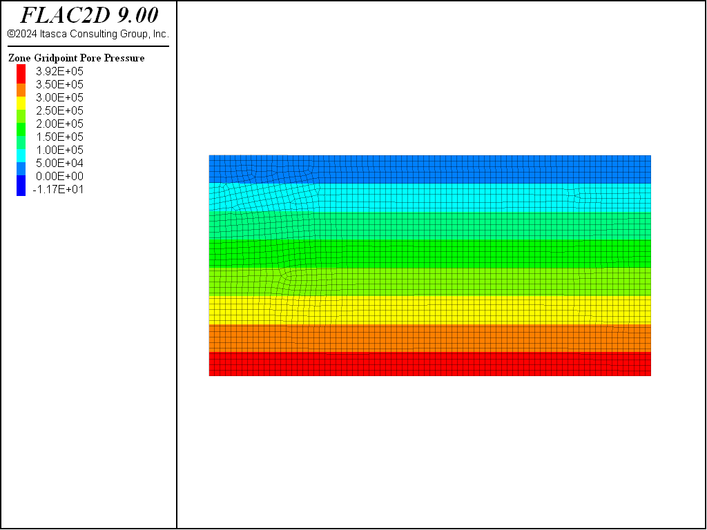
Figure 4: Initial pore-pressure distribution in foundation soils.
Embankment Construction - Unsupported
The embankment construction is analyzed assuming undrained conditions. This is accomplished by setting the groundwater flow calculation mode off and increasing the water bulk modulus to approximate a nearly incompressible fluid (0.2 GPa).
The unsupported embankment construction is simulated by adding each embankment-lift group individually by setting its constitutive model to Mohr-Coulomb, setting its properties and then solving for the equilibrium state with this lift in place. Note that the fluid properties are not required since a fluid flow analysis is not being performed (by default, porosity is 0.5). As each group is added, the saturation values of the gridpoints in the group are set to zero to simulate the unsaturated condition of the embankment materials. Figure 5 shows the model after adding the first lift. These steps are repeated for each of the three remaining foamed concrete lifts and the earth-fill lift. Finally, the traffic surcharge is applied along the top of the embankment. Each of the unsupported construction stages is saved as a separate save state.
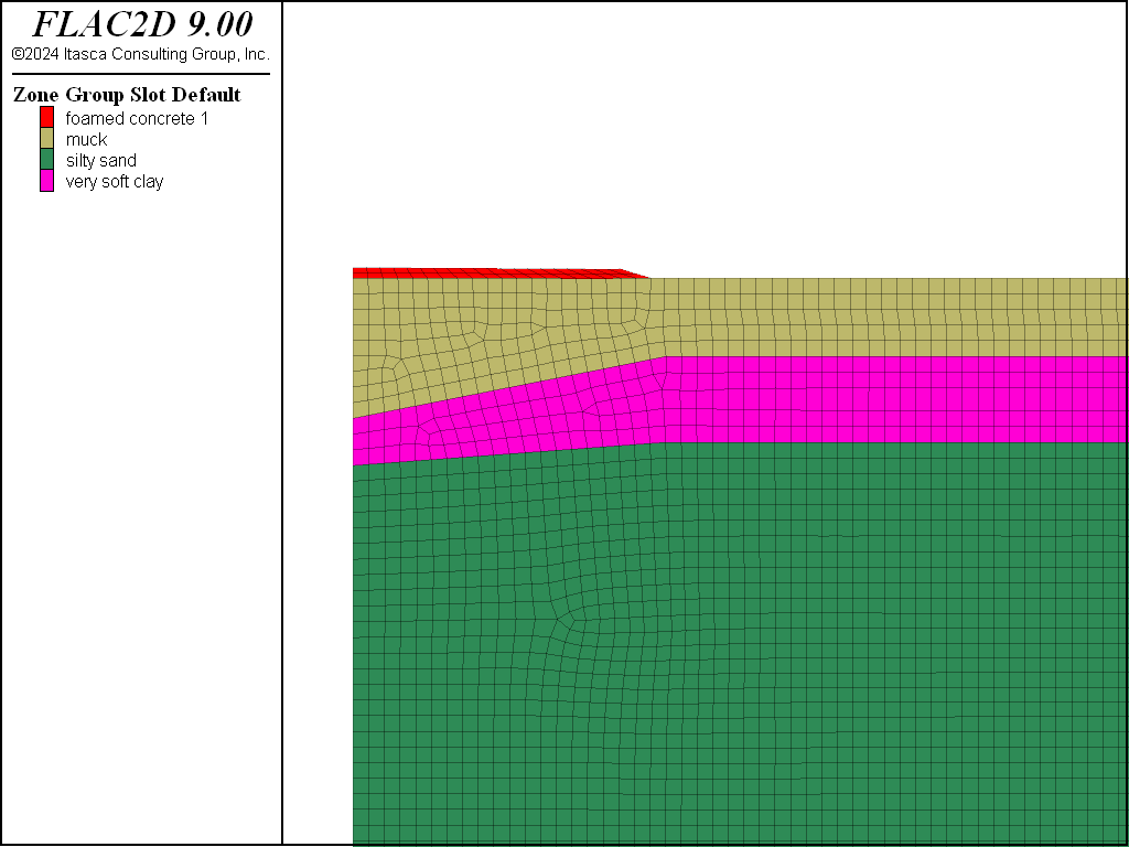
Figure 5: Addition of first embankment lift “foamed concrete 1”.
Vertical displacement histories are recorded at four locations along the base of the embankment at (\(x\) = 0,\(y\) = 0), (\(x\) = 6.5,`y` = 0), (\(x\) = 11.5,\(y\) = 0) and (\(x\) = 17,\(y\) = 0). The displacements are monitored throughout the embankment construction; the results are shown in Figure 6. The extent of the displacements induced by the unsupported construction is shown in Figure 7. The maximum vertical displacement beneath the embankment is approximately 0.7 m (2.3 ft).
The displacements are associated with excess pore pressures that develop in the muck and very soft clay. This is evident from the pore-pressure histories recorded along the centerline of the embankment at \(y\) = 0 and \(y\) = −6.5 (in the muck), and at \(y\) = −10.5 (in the very soft clay). The plots of pore-pressure histories are given in Figure 8.
A factor of safety calculation is performed at this stage using the command model factor-of-safety. The safety factor for the unsupported embankment is calculated to be 1.09. Figure 9 shows the failure surface that develops if cohesion and friction of the embankment and foundation materials are reduced by this factor. Note that for this model, the FOS calculation is quite sensitive to the solve ratio used. To get the most accurate result, the convergence approach is used (see Reaching Equilibrium). Also, large-strain must be turned off to perform an FOS analysis.
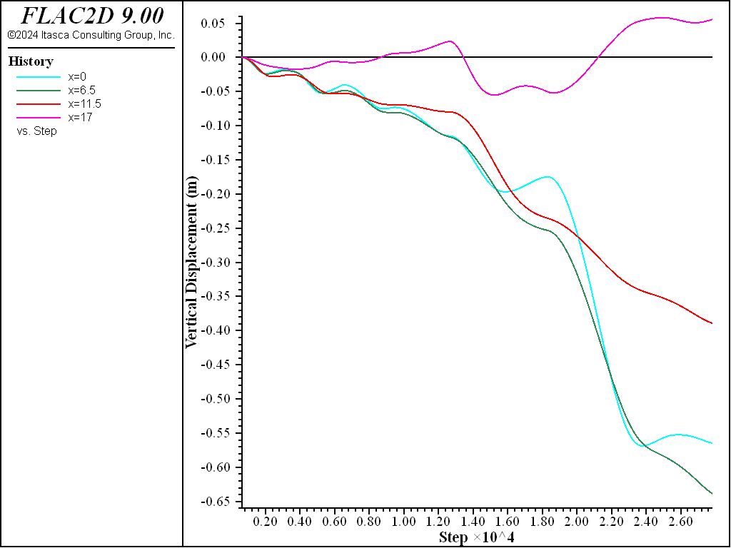
Figure 6: Vertical displacements along base of embankment for unsupported embankment construction.
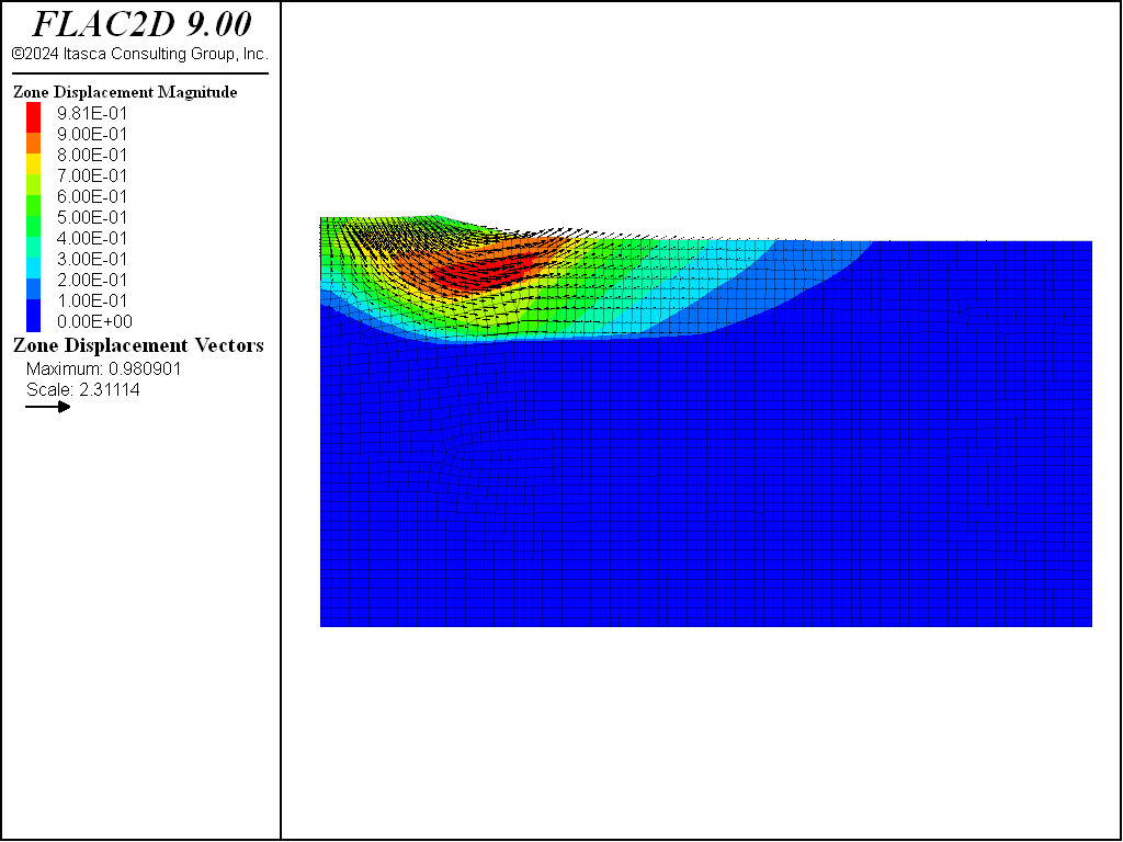
Figure 7: Displacements for unsupported embankment construction.
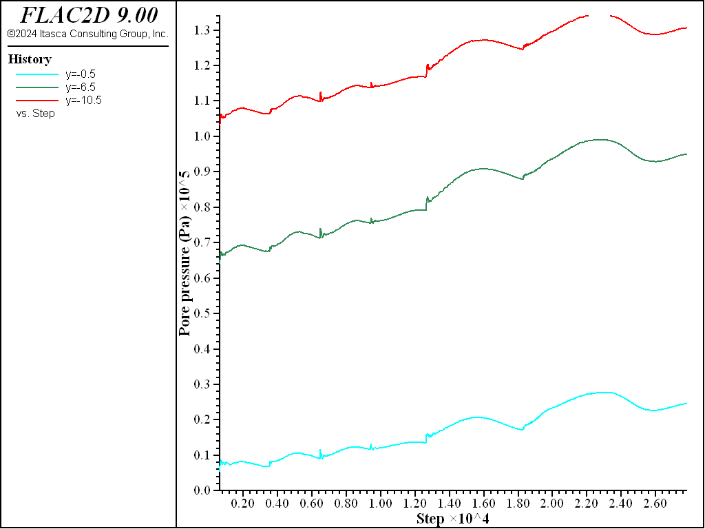
Figure 8: Pore pressures beneath center of embankment for unsupported embankment construction.
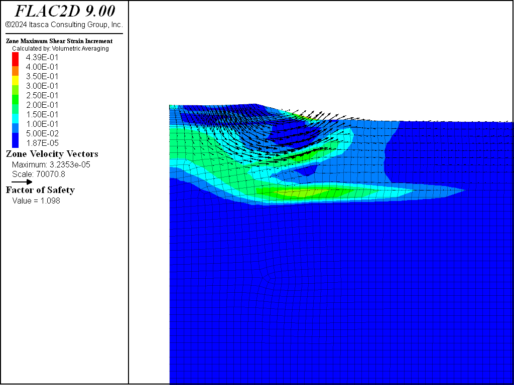
Figure 9: Factor of safety and failure surface plot for unsupported embankment.
Embankment Construction - Supported
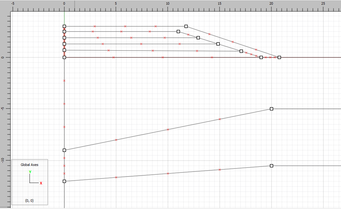
The pile-supported embankment construction is simulated by first installing pile elements in the FLAC2D model. The initial equilibrium state is restored, and seven piles of 12.8 m length are positioned at a 2.5 m spacing within the foundation soils. Before the piles are placed in the model, the first foamed concrete lift is added. This is done so that the top of the piles can be connected to the embankment materials. Then, the piles are positioned as shown in Figure 10.
In order to represent the three-dimensional effect of the 2.5 m pile spacing, the pile properties are scaled by dividing by the pile spacing. This is done automatically by specifying the spacing property when assigning pile properties. In this analysis, only the elastic modulus and the end-bearing capacity are scaled to account for the spacing. Note that the weight of the piles is neglected; the pile density would also be scaled if this weight is included.
The properties of the pile coupling springs are selected to simulate an end-bearing capacity and zero skin friction. The cohesive strengths of the shear coupling springs at the top and bottom elements of each pile are set to 2.5 MN/m, while all other shear and normal coupling-spring strength values are set to zero. The value for cohesive strength is derived from a simulation of axially loaded piles at 2.5 m spacing to produce an ultimate end-bearing capacity of 250 KN in the silty-sand foundation material. The value for coupling-spring shear stiffness is selected at approximately ten times the equivalent stiffness of the stiffest neighboring zone. By doing this, the deformability at the pile/soil interface will have minimal influence on both the compliance of the total model and the calculational speed. The properties used for the pile elements in this model are summarized in Table 3.
Another method for simulating end bearing capacity by specifying link stiffness and strength for the end node is described in the illustrative example Axially Loaded Pile: End Bearing.
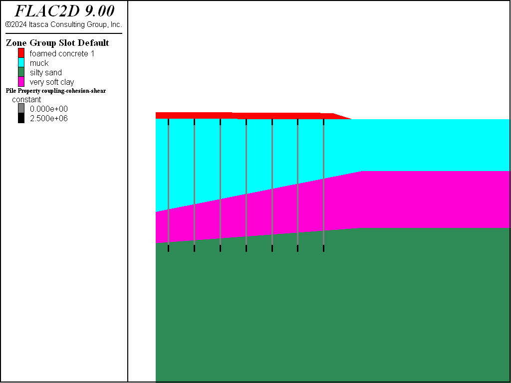
Figure 10: Location of piles in FLAC2D model.
Property |
middle segments |
top & bottom segments |
|---|---|---|
Elastic modulus (GPa) |
10 |
10 |
Radius (m) |
0.1524 |
0.1524 |
Spacing (m) |
2.5 |
2.5 |
Shear coupling spring stiffness (GN/m/m) |
0 |
1.0 |
Shear coupling spring cohesion (MN/m) |
0 |
2.5 |
Shear coupling spring friction (degrees) |
0 |
0 |
Normal coupling spring stiffness (GN/m/m) |
0 |
0 |
Normal coupling spring cohesion (MN/m) |
0 |
0 |
Normal coupling spring friction (degrees) |
0 |
0 |
The embankment construction steps are now performed following the same sequence of steps as in the unsupported case.
The vertical displacements are monitored as before; the histories are shown in Figure 11. The maximum vertical displacement beneath the embankment is now approximately 0.04 m (1.5 in).
Also, note that for this case there is an insignificant change in pore pressures in the muck and very soft clay, as seen in Figure 12.
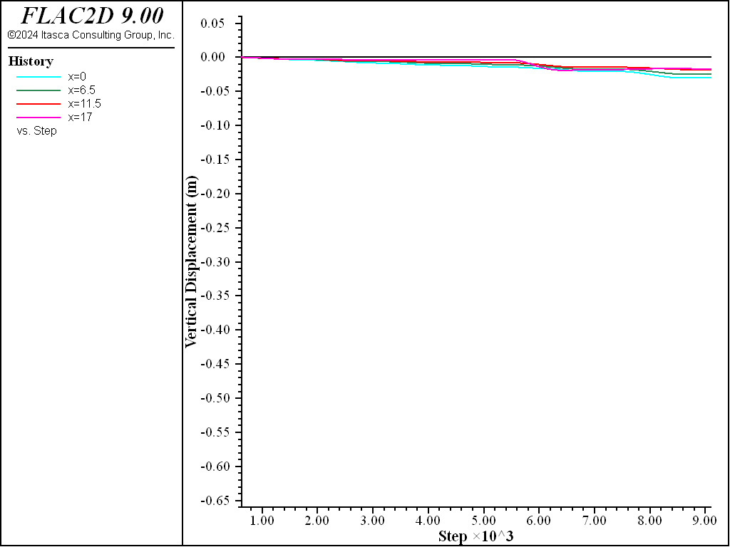
Figure 11: Vertical displacements along base of embankment for supported embankment construction.
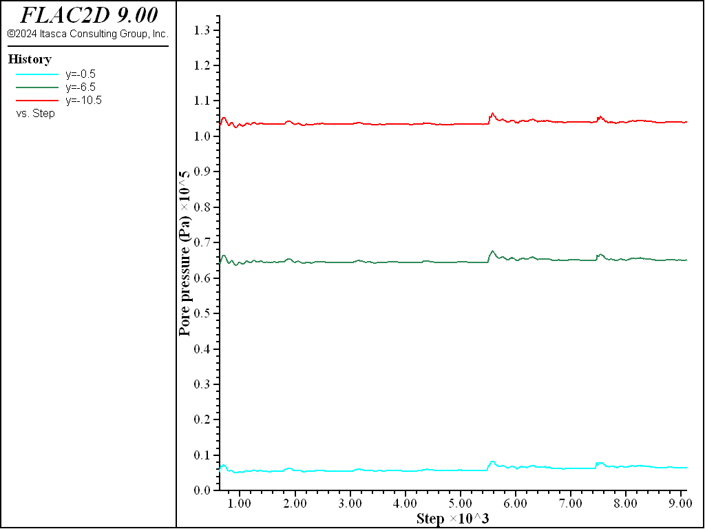
Figure 12: Pore pressures beneath center of embankment for supported embankment construction.
The axial loading that develops in the piles is also of interest. When the spacing property is assigned, the axial force values that are printed and plotted output are the actual values (i.e., they account for the pile spacing). The actual axial forces in the piles are plotted in Figure 13. The maximum pile loading is approximately 230 KN.
A factor of safety calculation is also performed at this stage. The calculated factor is 2.3, and the failure surface is shown by the plot in Figure 14. Note that the critical failure surface for the supported embankment is now along the slope of the earthfill berm. The safety factor for the foundation material beneath the embankment is greater than 2.3 as a result of the support provided by the piles.
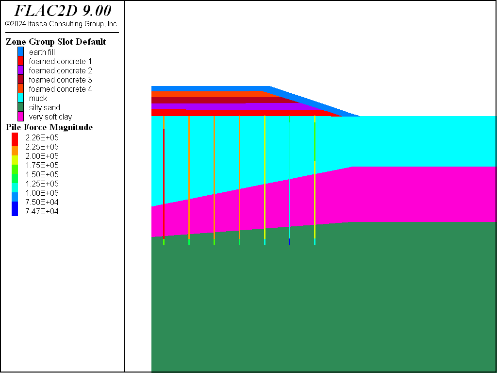
Figure 13: Axial loads in files for supported embankment construction.
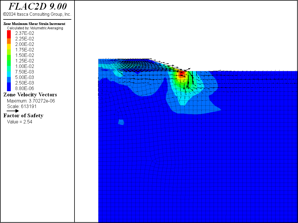
Figure 14: Factor of safety and failure surface plot for supported embankment.
Data Files
initial.dat
model new
program call 'modelpane'

model configure fluid

model gravity 9.81

; apply boundary conditions before nulling embankment
zone face apply velocity-x 0 range group 'East' or 'West'
zone face apply velocity 0 0 range group 'Bottom'

; null embankment
zone cmodel assign null range group 'earth fill'
zone cmodel assign null range group 'foamed concrete 1'
zone cmodel assign null range group 'foamed concrete 2'
zone cmodel assign null range group 'foamed concrete 3'
zone cmodel assign null range group 'foamed concrete 4'

; fluid properties
zone fluid cmodel assign anisotropic
zone water density 1000
zone gridpoint initialize fluid-modulus 1e4

zone fluid property porosity 0.3 range group 'silty sand'

; convert m/day to m/s
zone fluid property  hydraulic-conductivity-xx [2.4/(24*60*60)] ...
  hydraulic-conductivity-yy [0.8/(24*60*60)] ...
  range group 'silty sand'

zone fluid property porosity 0.8 ...
  hydraulic-conductivity-xx [0.0003/(24*60*60)] ...
  hydraulic-conductivity-yy [0.0001/(24*60*60)] ...
  range group 'very soft clay'

zone fluid property porosity 0.9 ...
  hydraulic-conductivity-xx [0.003/(24*60*60)] ...
  hydraulic-conductivity-yy [0.001/(24*60*60)] ...
  range group 'muck'

; initial conditions

; set water table first, so effective stresses are set
; for horizontal initial stresses
zone water plane normal 0,-1 origin 0,0

; Initial vertical stress is defined by a table of y-coordinate
;    vs vertical stress.
; Note that table points must be sorted by increasing x value
table '1' add (-40,-6.8586E5) (-10.5,-1.3008E5) (-5,-5.55E4) (0,0)

; now set stresses by interpolating table values
fish define set_stress(ratiox, ratioz)
  loop foreach local zp zone.list
    local y = zone.pos.y(zp)
    local syy = table('1',y)
    zone.stress.yy(zp) = syy

    local pp = zone.pp(zp)
    zone.stress.xx(zp) = (syy+pp)*ratiox - pp
    zone.stress.zz(zp) = (syy+pp)*ratioz - pp
  end_loop
end
[set_stress(0.5,0.5)]

model large-strain on
zone nodal-mixed-discretization off

model solve elastic
model save 'initial'
unsupported.dat
model restore 'initial'

zone gridpoint initialize displacement 0 0

zone gridpoint initialize fluid-modulus 2e8
zone gridpoint initialize fluid-tension 0

zone history name 'x=0' displacement-y position 0,0
zone history name 'x=6.5' displacement-y position 6.5,0
zone history name 'x=11.5' displacement-y position 11.5,0
zone history name 'x=17' displacement-y position 17,0

zone history name 'y=-0.5' pore-pressure position 0,-0.5
zone history name 'y=-6.5' pore-pressure position 0,-6.5
zone history name 'y=-10.5' pore-pressure position 0,-10.5
zone history name 'y=-24' pore-pressure position 0,-24

; mechanical properties for fill
zone cmodel assign mohr-coulomb range group 'foamed concrete 1'
zone property density 600 young 640e6 poisson 0.15 ...
  cohesion 50000 range group 'foamed concrete 1'

; set saturation to 0 for nodes in the fill
zone gridpoint initialize saturation 0 range group 'foamed concrete 1' ...
  position-y 0.1 0.71

model fluid active off
model solve

model save 'unsupported-lift1'

=========================================

; add lift 2
zone cmodel assign mohr-coulomb range group 'foamed concrete 2'
zone property density 600 young 640e6 poisson 0.15 ...
  cohesion 50000 range group 'foamed concrete 2'

; set saturation to 0 for nodes in the fill
zone gridpoint initialize saturation 0 range group 'foamed concrete 2' ...
  position-y 0.71 1.31

model solve

model save 'unsupported-lift2'

=========================================

; lift 3
zone cmodel assign mohr-coulomb range group 'foamed concrete 3'
zone property density 600 young 640e6 poisson 0.15 ...
  cohesion 50000 range group 'foamed concrete 3'

; set saturation to 0 for nodes in the fill
zone gridpoint initialize saturation 0 range group 'foamed concrete 3' ...
  position-y 1.31 1.91

model solve

model save 'unsupported-lift3'

=========================================

; lift 4
zone cmodel assign mohr-coulomb range group 'foamed concrete 4'
zone property density 600 young 640e6 poisson 0.15 ...
  cohesion 50000 range group 'foamed concrete 4'

; set saturation to 0 for nodes in the fill
zone gridpoint initialize saturation 0 range group 'foamed concrete 4' ...
  position-y 1.91 2.51

model solve

model save 'unsupported-lift4'

=========================================

; earth fill
zone cmodel assign mohr-coulomb range group 'earth fill'
zone property density 1920 young 10e6 poisson 0.3 ...
  cohesion 2400 friction 30 range group 'earth fill'

; set saturation to 0 for nodes in the fill
zone gridpoint initialize saturation 0 range group 'earth fill' ...
  position-y 0.1 3.01

model solve

model save 'unsupported-earthfill'

=============================================

; Apply surcharge.
; Be careful with the range - top surface will have moved downwards
zone face apply stress-yy -11500 range position-x 0 11.3 position-y 2.8 3

model solve
model save 'unsupported-surcharge'

========================================

; compute factor of safety
model large-strain off
model factor-of-safety convergence 1 filename 'unsupported'
supported.dat
model restore 'initial'

zone gridpoint initialize displacement 0 0

zone gridpoint initialize fluid-modulus 2e8
zone gridpoint initialize fluid-tension 0

zone history name 'x=0' displacement-y position 0,0
zone history name 'x=6.5' displacement-y position 6.5,0
zone history name 'x=11.5' displacement-y position 11.5,0
zone history name 'x=17' displacement-y position 17,0

zone history name 'y=-0.5' pore-pressure position 0,-0.5
zone history name 'y=-6.5' pore-pressure position 0,-6.5
zone history name 'y=-10.5' pore-pressure position 0,-10.5
zone history name 'y=-24' pore-pressure position 0,-24

; mechanical properties for fill
zone cmodel assign mohr-coulomb range group 'foamed concrete 1'
zone property density 600 young 640e6 poisson 0.15 ...
  cohesion 50000 range group 'foamed concrete 1'

; set saturation to 0 for nodes in the fill
zone gridpoint initialize saturation 0 range group 'foamed concrete 1' ...
  position-y 0.1 0.71

; create piles - put top node in concrete
structure pile create by-line 1.25,0.05 1.25,-12.8 segments 20
structure pile create by-line 3.75,0.05 3.75,-12.8 segments 20
structure pile create by-line 6.25,0.05 6.25,-12.8 segments 20
structure pile create by-line 8.75,0.05 8.75,-12.8 segments 20
structure pile create by-line 11.25,0.05 11.25,-12.8 segments 20
structure pile create by-line 13.75,0.05 13.75,-12.8 segments 20
structure pile create by-line 16.25,0.05 16.25,-12.8 segments 20

; frictionless piles
[radius = 0.1524]
structure pile property spacing 2.5 young 1e10 poisson 0.3 ...
  cross-sectional-area=[math.pi*radius*radius] ...
  coupling-stiffness-normal=0 coupling-stiffness-shear 0 ...
  moi [math.pi*radius^4/4.0]

; anchor at the top and bottom
structure pile property coupling-stiffness-shear=1.0e9 ...
  coupling-cohesion-shear=2.5e6 range position-y -0.6 0.05
structure pile property coupling-stiffness-shear=1.0e9 ...
  coupling-cohesion-shear=2.5e6 range position-y -12.8 -12.2

model fluid active off
model solve

model save 'supported-lift1'

========================================

; add lift 2
zone cmodel assign mohr-coulomb range group 'foamed concrete 2'
zone property density 600 young 640e6 poisson 0.15 ...
  cohesion 50000 range group 'foamed concrete 2'

; set saturation to 0 for nodes in the fill
zone gridpoint initialize saturation 0 range group 'foamed concrete 2' ...
  position-y 0.71 1.31

model solve

model save 'supported-lift2'

=========================================

; lift 3
zone cmodel assign mohr-coulomb range group 'foamed concrete 3'
zone property density 600 young 640e6 poisson 0.15 ...
  cohesion 50000 range group 'foamed concrete 3'

; set saturation to 0 for nodes in the fill
zone gridpoint initialize saturation 0 range group 'foamed concrete 3' ...
  position-y 1.31 1.91

model solve

model save 'supported-lift3'

=========================================

; lift 4
zone cmodel assign mohr-coulomb range group 'foamed concrete 4'
zone property density 600 young 640e6 poisson 0.15 ...
  cohesion 50000 range group 'foamed concrete 4'

; set saturation to 0 for nodes in the fill
zone gridpoint initialize saturation 0 range group 'foamed concrete 4' ...
  position-y 1.91 2.51

model solve

model save 'supported-lift4'

=========================================

; earth fill
zone cmodel assign mohr-coulomb range group 'earth fill'
zone property density 1920 young 10e6 poisson 0.3 ...
  cohesion 2400 friction 30 range group 'earth fill'

; set saturation to 0 for nodes in the fill
zone gridpoint initialize saturation 0 range group 'earth fill' ...
  position-y 0.1 3.01

model solve

model save 'supported-earthfill'

=============================================

; Apply surcharge.
; Be careful with the range - top surface will have moved downwards
zone face apply stress-yy -11500 range position-x 0 11.3 position-y 2.8 3

model solve
model save 'supported-surcharge'

========================================

; compute factor of safety
model large-strain off
model factor-of-safety convergence 1 filename 'supported'
Endnotes
⇐ Multistage Tunnel Excavation and Support (FLAC2D) | Example: FOS Calculated for Jointed Rock Slopes ⇒
| Was this helpful? ... | Itasca Software © 2024, Itasca | Updated: Apr 02, 2024 |
