Advancing Lined Tunnel (Slip at Liner-Soil Interface)
Problem Statement
Note
To view this project in 3DEC, use the menu command . Choose “BlockSel/ Liner/ AdvancingLinedTunnel” and select “AdvancingLinedTunnel.prj” to load. The main data file used is shown at the end of this example. The remaining data files can be found in the project.
This example demonstrates how to simulate the sequential operations of excavating and adding support to an advancing tunnel. The tunnel has a circular cross-section and is located at 5 m depth in a soft elastic soil (\(E\) = 48.2 MPa, \(\nu\) = 0.34) with isotropic in-situ stresses of 1 MPa. The tunnel is supported by shotcrete (\(E\) = 10.5 GPa, \(\nu\) = 0.25) with a thickness of 0.2 m. The shotcrete remains elastic; however, the liner-soil interface can separate and/or slip. This example replicates the Advancing Lined Tunnel (Rigidly Connected) example, but replaces the shell elements used in that example with the liner elements used here. The shell elements provide a rigid connection with the soil, whereas the liner elements provide an elastic connection that allows gaps to form and slip to occur. In this example, first a large cohesive strength is assigned to the soil-liner interface to reproduce the rigid behavior from the shell element version, and then we set the cohesive strength to zero and observe the slip and resulting stress redistribution.
Begin with an initial tunnel of 2 m total length. For simplicity, it is assumed that the excavation proceeds simultaneously on both tunnel faces; therefore, it is only necessary to model one quarter-section of the tunnel by applying symmetry boundary conditions on the three symmetry planes. (Specifying the proper symmetry conditions to the nodes on these planes requires first aligning the node-local systems, as described below.) The excavation process is modeled by assigning the null material model to zones, then allowing the stresses to redistribute. The model at this stage is shown in Figure 1. Now the shotcrete is installed by creating liner elements and attaching them to the tunnel surface with the structure liner create by-block-face command. The next tunnel segment is excavated and, again, the stresses are allowed to redistribute. The model at this stage is shown in Figure 2. This excavation sequence can be repeated to follow the entire tunnel construction.
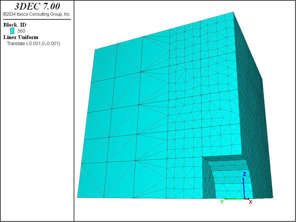
Figure 1: Stage 1: Excavate tunnel section 1.
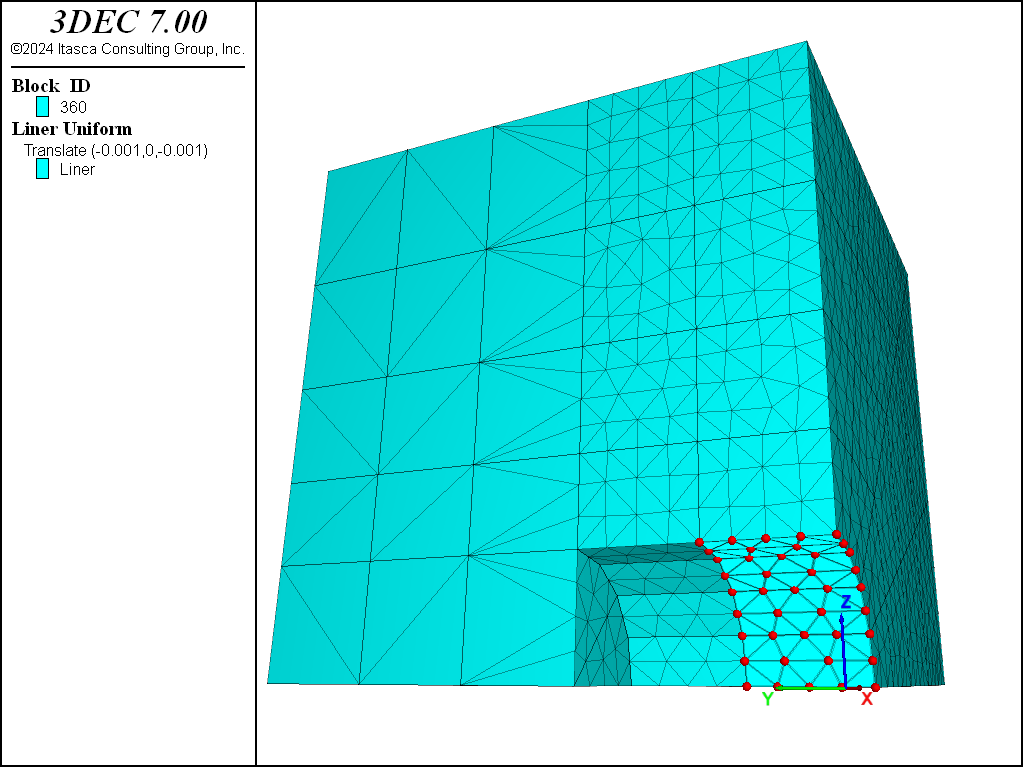
Figure 2: Stage 2: Install shotcrete in section 1; excavate tunnel section 2.
There are three symmetry planes in this model. Symmetry boundary conditions (zero displacement normal to the plane, and zero rotation about two axes that lie in the plane) must be specified for the nodes that lie upon these planes. These conditions are specified using the structure node fix command; however, this command operates on the degrees of freedom associated with the node-local system, and the node-local systems of all nodes used by liner elements are set automatically at the start of a set of cycles (or when the model cycle 0 command is executed), such that the \(z\)-axis is aligned with the average normal direction of all liner elements using the node, and the \(xy\)-axes are arbitrarily oriented in the liner element tangent plane. For this model, the default orientation is shown in Figure 3.
Nodes lying on the \(x\) = 0 and \(z\) = 0 planes must be reoriented in order to specify the proper symmetry boundary conditions. This is accomplished with the commands
struct node system-local x (1,0,0) y (0,-1,0)    range position-x 0
struct node fix system-local                     range position-x 0
struct node fix velocity-x rotation-y rotation-z range position-x 0
struct node system-local x (0,0,-1) y (0,-1,0)   range position-z 0
struct node fix system-local                     range position-z 0
struct node fix velocity-x rotation-y rotation-z range position-z 0
struct node fix velocity-y rotation-x rotation-z range position-y 0
These commands realign and then fix the appropriate node-local systems and also specify the proper
velocity-fixity conditions. The realigned systems must be fixed with the
structure node fix system-local command in order to prevent automatic realignment to the default
orientation during the next set of cycles. When realigning these systems, we must ensure that the local
\(z\)-axis remains normal to the liner tangent plane, because the node-local orientations define the
liner-zone attachment conditions. The final, realigned node-local system orientations are shown in
Figure 4.
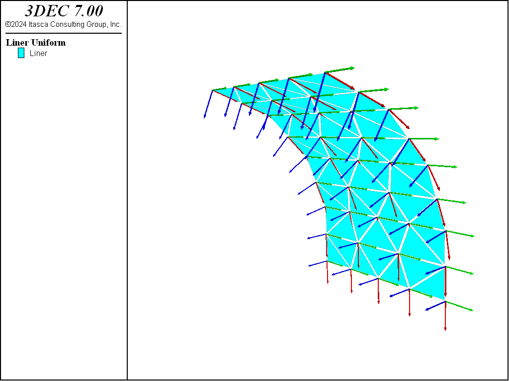
Figure 3: Default orientation of node-local systems.
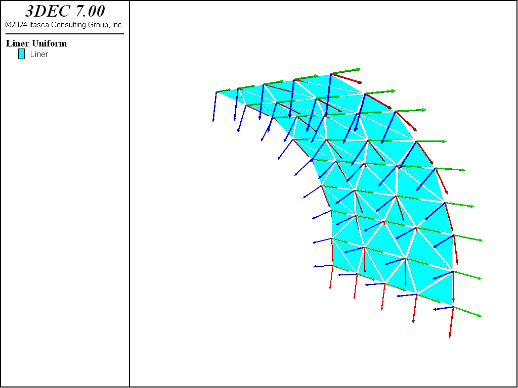
Figure 4: Orientation of node-local systems after realignment.
The liner-zone interface stiffnesses (\(k_n\) and \(k_s\)) are set equal to 7.4 × 10¹⁰ N/m3 to ensure that the interface deformation is small relative to the zone deformation using the liner stiffness equation, and increasing the value by a factor of 100, as suggested in the text following this equation. (We will confirm below that the criterion of small interface deformation is met for our system.)
In the first run, a large cohesive strength is assigned to the liner-zone interface. The behavior of this model should be similar to the behavior of the rigidly connected system. Figure 5 and Figure 6 show the displacements that occur during the second excavation stage for the case with no support and with support, respectively. The \(z\)-displacement history at the tunnel crown is included in each figure. See that the support reduces the crown displacement from approximately 12 mm to 1 mm.
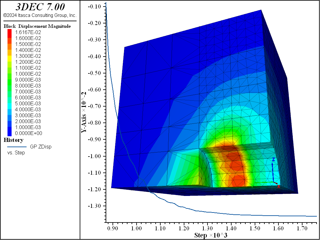
Figure 5: Displacements during stage 2—no support.
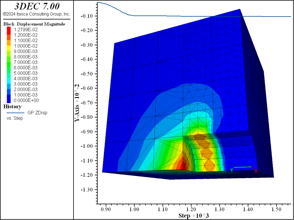
Figure 6: Displacements during stage 2—shotcrete support (liner-zone cohesion = 1020).
The bending stress resultant, \(M_x\), where the \(x\)-direction lies along the tunnel axis, is shown in Figure 7. We see that bending is most extreme at the front of the liner near the tunnel face. A plot of the deformed shape of the liner in Figure 8 indicates that this intense bending arises from the large pinching deformation. These two plots can be compared with the corresponding figures from the shell element version. The close similarity indicates that the system is behaving like the rigidly connected case.
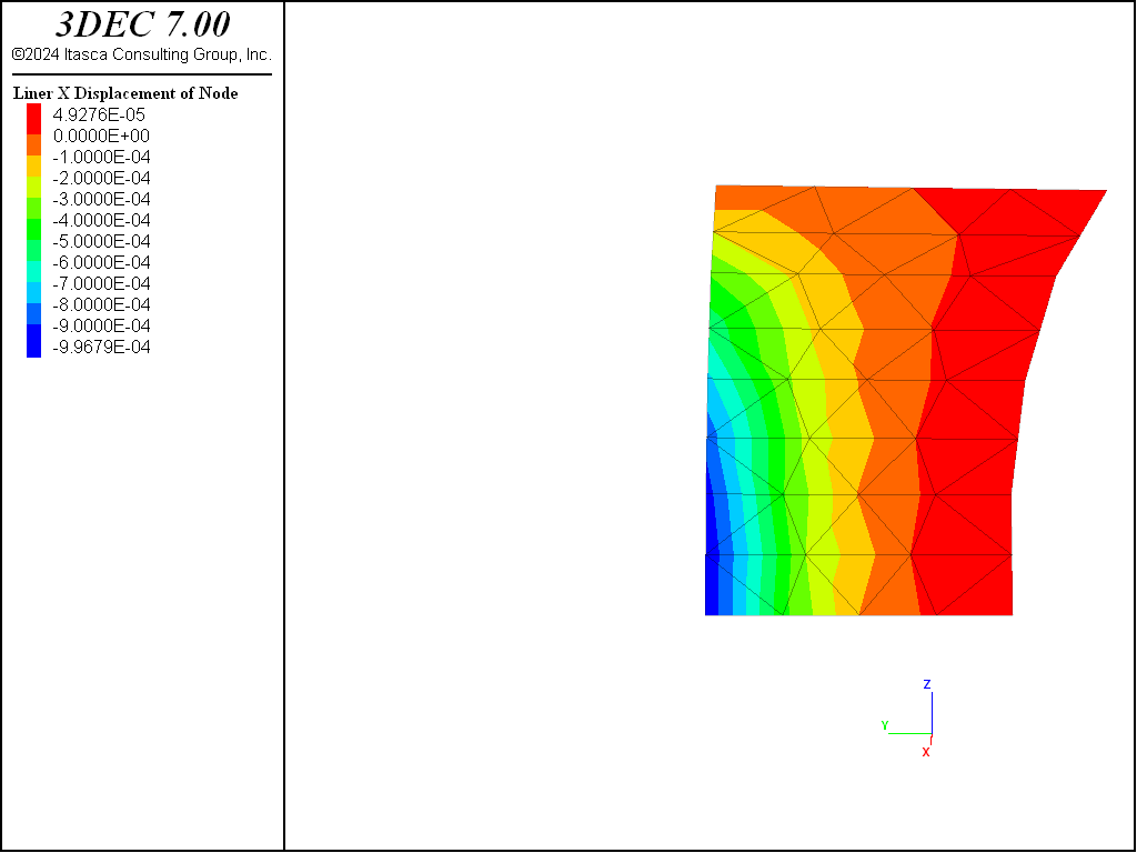
Figure 7: Bending stress resultant, \(M_x\), at end of stage 2 (liner-zone cohesion = 1020).
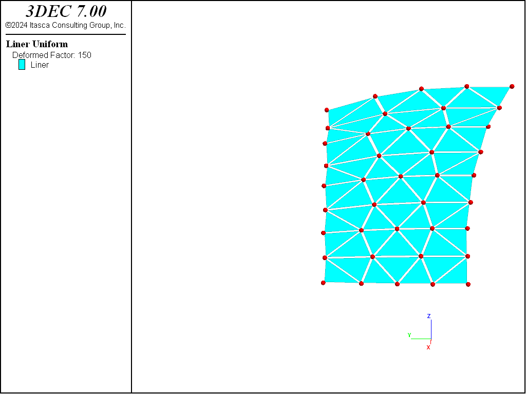
Figure 8: Deformed (magnification of 150) shape of shotcrete at end of stage 2 (liner-zone cohesion = 10 20).
It is confirmed that the interface deformation is small relative to the zone deformation (and thus confirm that our values of \(k_n\) and \(k_s\) are large enough) by plotting the normal displacement of the gridpoint, node and coupling spring at the tunnel crown (see Figure 9). If the model is rerun with values of \(k_n\) and \(k_s\) that are 100 times smaller than the current values, it is found that the interface deformation is no longer small relative to the zone deformation (see Figure 10). This leads to lower loads being carried in the liner. The maximum value of bending stress resultant, \(M_x\), is 44% less than its previous value (compare Figure 11 and Figure 7). In order to obtain the proper system response, the values of \(k_n\) and \(k_s\) must be large enough to keep the interface deformation small relative to the zone deformation.
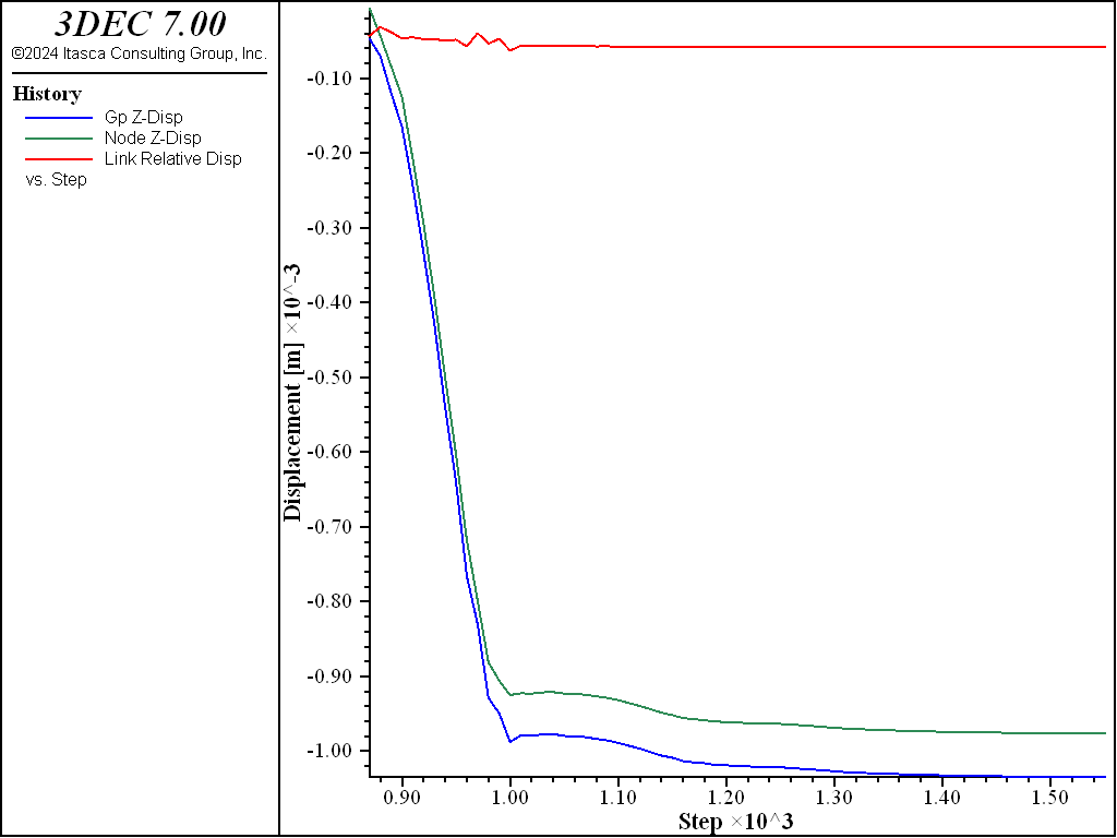
Figure 9: Normal displacement of gridpoint, node, and coupling spring at tunnel crown at end of stage 2 (liner-zone cohesion = 1020).
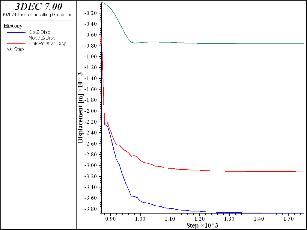
Figure 10: Normal displacement of gridpoint, node, and coupling spring at tunnel crown at end of stage 2 (\(k_n\) and \(k_s\) reduced by factor of 100; liner-zone cohesion = 1020).
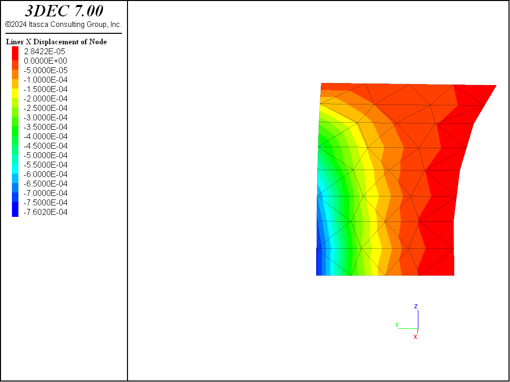
Figure 11: Bending stress resultant, \(M_x\), at end of stage 2 (\(k_n\) and \(k_s\) reduced by factor of 100; liner-zone cohesion = 1020).
The normal and shear stresses acting on the liner at the end of stage 2 are shown in Figure 12 and Figure 13. Both stresses are largest near the front of the liner near the tunnel face. These stresses are causing the pinching deformation seen in Figure 8. If the cohesive strength of the soil-liner interface is set to zero and cycled to equilibrium, it is observed that the liner springs back in the negative global \(y\)-direction (see Figure 14) as the shear stresses acting on the liner go to zero. The normal stresses acting on the liner and the bending stress resultant, \(M_x\), are only minimally affected.
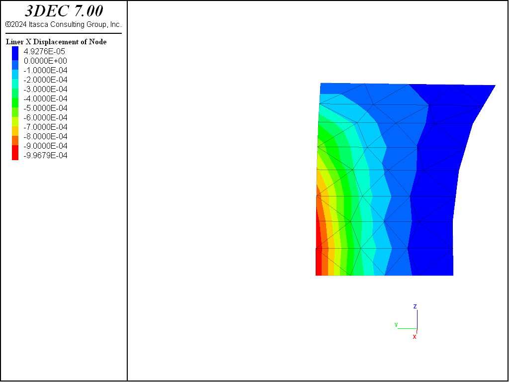
Figure 12: Normal stress acting on liner surface at end of stage 2 (liner-zone cohesion = 1020).
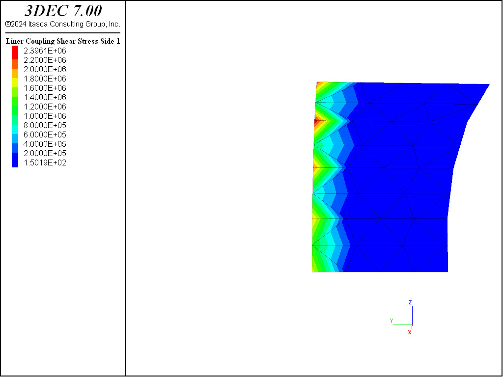
Figure 13: Shear stress acting on liner surface at end of stage 2 (liner-zone cohesion = 1020).
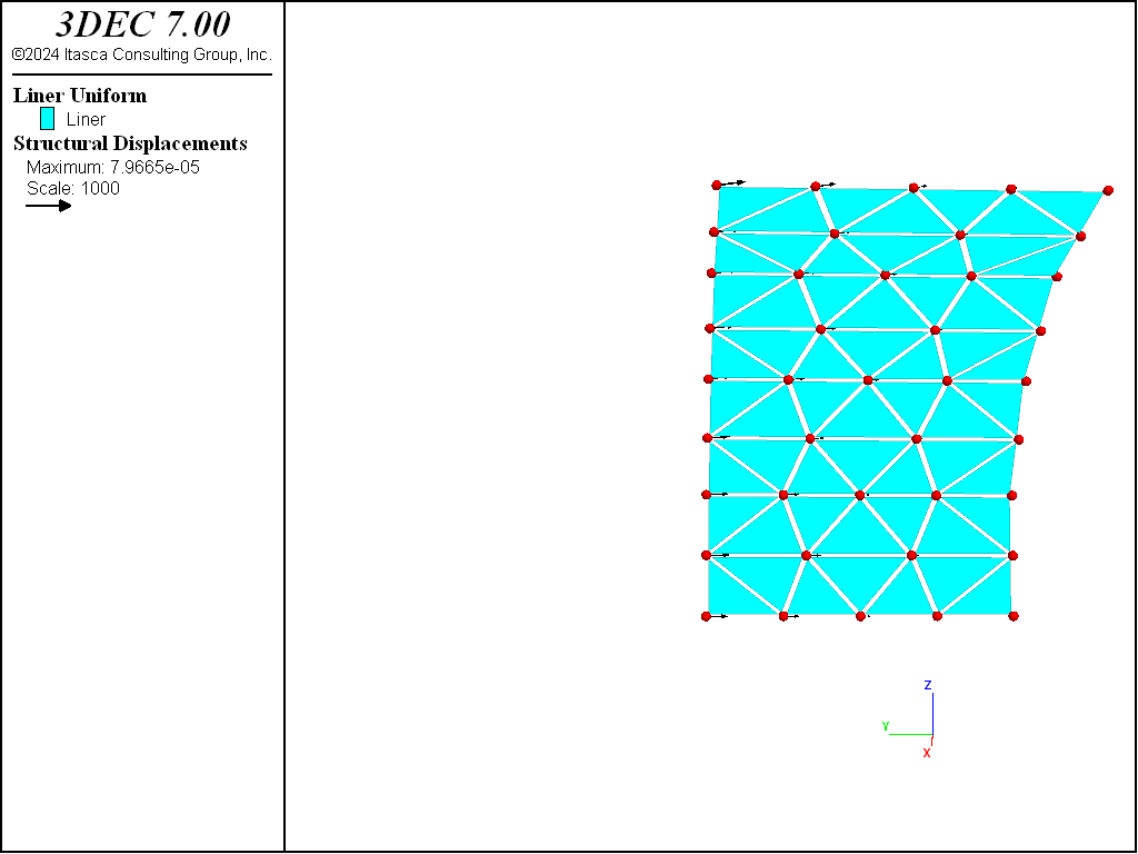
Figure 14: Liner displacement produced by setting the liner-zone cohesion to zero after stage 2.
One additional excavation stage is performed. The model at the end of this stage is shown in
Figure 15. The shotcrete support has been extended into tunnel section 2 by
issuing another structure liner create by-block-face command and specifying an ID number that differs
from the ID number of the liner in tunnel section 1. This creates a “cold-joint” between the two
shotcrete segments. (There will be a collection of double nodes lying along the interface, one of which
is used by segment one, and one used by segment two. Forces and moments will not be transferred
between the adjoining liner elements; instead, only forces will be transmitted into the surrounding zones
at the common locations. This mimics two separate liner segments lying next to one another.) The
deformation that occurs during stage 3 begins to load the new liner segment and produces additional load
in the previous liner segment. Both the displacement and the bending stress fields (see
Figure 16) are discontinuous across the joint.
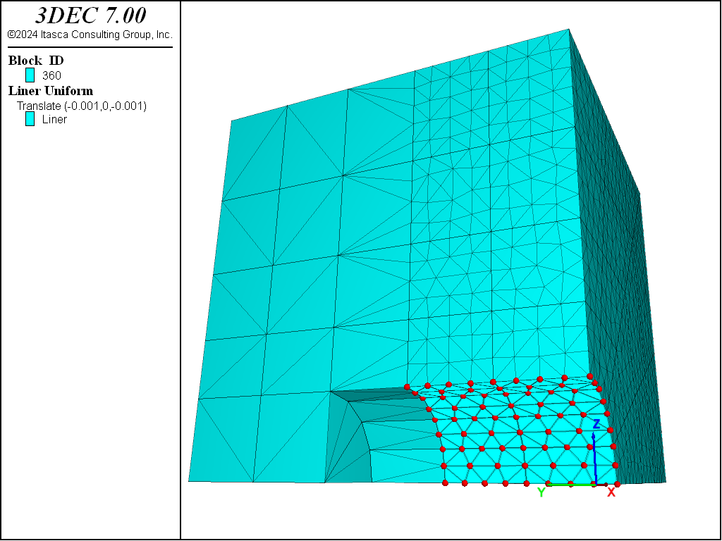
Figure 15: Stage 3: Install shotcrete in section 2; excavate tunnel section 3.
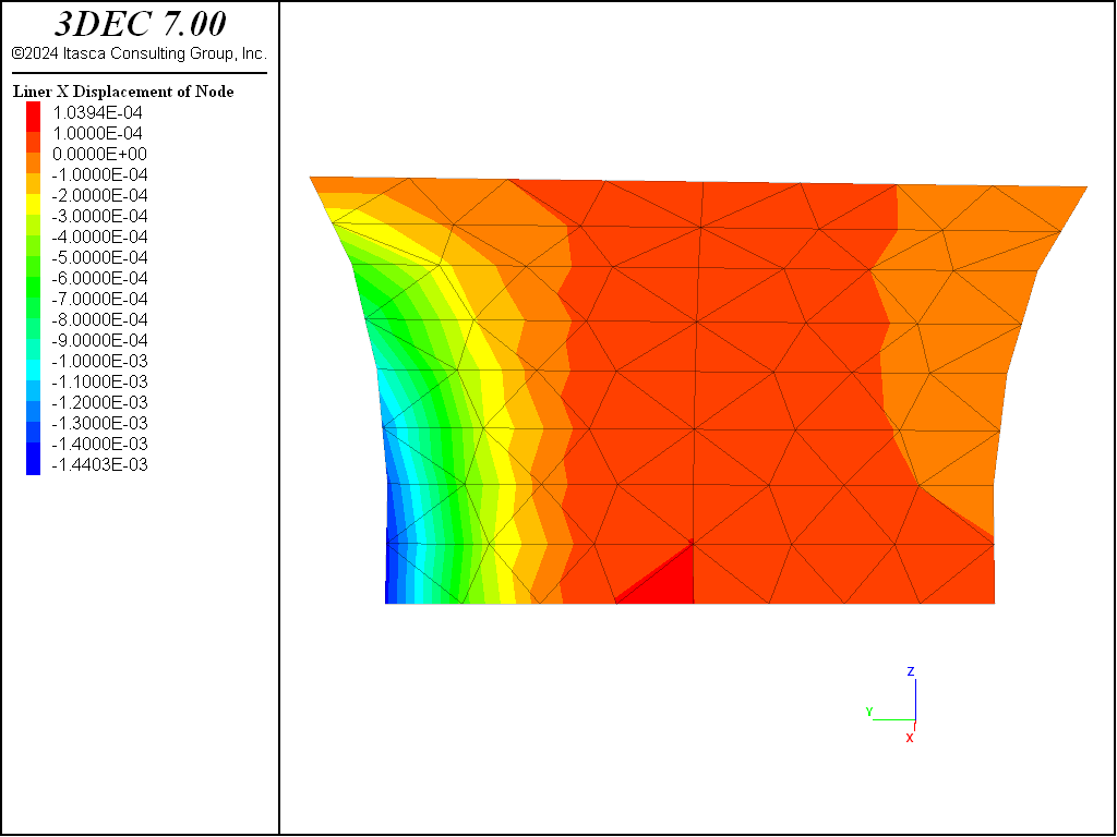
Figure 16: Bending stress resultants, \(M_x\), at end of stage 3 (liner-zone cohesion of zero).
Data File
AdvancingLinedTunnel.dat
; SEL Liner example application :
; Advancing Lined Tunnel with Slip at Liner-Soil interface
model new
model random 10000
model large-strain off
fish automatic-create off
model title 'Advancing Lined Tunnel with Slip (using liners)'
; Create model geometry
block create tunnel radius 1.0 length 0 5 ...
  blocks-radial 4 blocks-tangential 2 blocks-axial 5 radius-ratio 1.1
block join

; assume quarter symmetry
block delete range pos-x -5 0
block delete range pos-z -5 0

block group 'rock'
block group 'tunnel' range cylinder end-1 0 0 0 end-2 0 5 0 radius 1

block zone generate edgelength 0.25 range pos-y 0 2
block zone generate edgelength 1.0 range pos-y 2 5

; Name regions of the model
block group 'section1' range position-y 0 1 group 'tunnel'
block group 'section2' range position-y 1 2 group 'tunnel'
block group 'section3' range position-y 2 3 group 'tunnel'
block group 'section4' range position-y 3 4 group 'tunnel'
block group 'section5' range position-y 4 5 group 'tunnel'
block face group 'shotcrete1' range group-intersection 'rock' 'section1'
block face group 'shotcrete2' range group-intersection 'rock' 'section2'
block face group 'shotcrete3' range group-intersection 'rock' 'section3'

; Material model and properties
block zone cmodel assign elastic
block zone property dens 2000 bulk 50e6 shear 18e6

; contact properties for excavated blocks
block contact material-table default prop stiff-norm 1e8 stiff-shear 1e8

; Initial Conditions
block insitu stress -1e6 -1e6 -1e6 0 0 0

; Boundary Conditions
block gridpoint apply velocity-x 0 range position-x 0.0
block gridpoint apply velocity-y 0 range position-y 0.0
block gridpoint apply velocity-z 0 range position-z 0.0
block gridpoint apply velocity 0 0 0 range union position-x 5.0 ...
                                                 position-y 5.0 ...
                                                 position-z 5.0

; --- Stage 1: excavate tunnel section 1
block excavate range group 'section1'
model solve
model save 'tun1'
;
; --- Stage 2: excavate tunnel section 2
block gridpoint initialize displacement (0,0,0)
block history name 'zdisp' displacement-z position (0,1,1)
block history name 'zvel' velocity-z position (0,1,1)
block excavate range group 'section2'
model save 'tun2-initial'

; --- Solve case with no support
model solve
model save 'tun2-nosupport'

; --- Solve case with shotcrete
model restore 'tun2-initial'
struct liner create by-block-face id=1 range group 'shotcrete1'
struct liner property isotropic=(10.5e9, 0.25) thickness=0.2
struct liner property coupling-stiffness-normal=7.4e10 ...
                      coupling-stiffness-shear=7.4e10  ...
                      coupling-cohesion-shear=1e20
model cycle 0
model save 'tun2-temp1'

; --- Specify symmetry conditions for nodes along the 3 symmetry planes
struct node system-local x (1,0,0) y (0,-1,0)    range position-x 0
struct node fix system-local                     range position-x 0
struct node fix velocity-x rotation-y rotation-z range position-x 0
struct node system-local x (0,0,-1) y (0,-1,0)   range position-z 0
struct node fix system-local                     range position-z 0
struct node fix velocity-x rotation-y rotation-z range position-z 0
struct node fix velocity-y rotation-x rotation-z range position-y 0
struct node history name 'znode' displacement-z position 0 1 1
struct liner history name 'ndis' coupling-displacement-normal ...
                     node 3 component-id=45
model cycle 0
model save 'tun2-temp2'
model solve
model save 'tun2a'

; Repeat excavation with lower stiffnesses (factor 100)
model restore 'tun2-temp2'
struct liner property coupling-stiffness-normal=7.4e8 ...
                      coupling-stiffness-shear=7.4e8  ...
                      coupling-cohesion-shear=1e20
model solve
model save 'tun2a-lowstiff'

; Pursue excavation with larger stiffnesses (reduce cohesion)
model restore 'tun2a'
struct node initialize displacement (0,0,0)
struct liner property coupling-cohesion-shear=0.0
model solve
model save 'tun2b'

; --- Stage 3: excavate tunnel section 3
block excavate range group 'section3'
struct liner create by-block-face id=2 range group 'shotcrete2'
; --- Specify symmetry conditions for nodes along the 3 symmetry planes
struct node system-local x (1,0,0) y (0,-1,0)    range position-x 0
struct node fix system-local                     range position-x 0
struct node fix velocity-x rotation-y rotation-z range position-x 0
struct node system-local x (0,0,-1) y (0,-1,0)   range position-z 0
struct node fix system-local                     range position-z 0
struct node fix velocity-x rotation-y rotation-z range position-z 0
struct node fix velocity-y rotation-x rotation-z range position-y 0
struct liner property isotropic=(10.5e9, 0.25) thickness=0.2 range id 2
struct liner property coupling-stiffness-normal=7.4e10 ...
                      coupling-stiffness-shear=7.4e10  ...
                      coupling-cohesion-shear=0.0 range id 2
model solve convergence 1
model save 'tun3'
| Was this helpful? ... | 3DEC © 2019, Itasca | Updated: Feb 25, 2024 |