Identifying Regions of the Model
Once a mesh has been created (see Grid Generation), the next problem to confront a user is how to identify the zones and zone faces that make up areas of interest in the model. In a complex three-dimensional model, this can be particularly troublesome. In point of fact, in the past, a great deal of the difficulty perceived in creating a data file was simply the problem of how to specify the zones or faces desired for a given command.
Some of this will generally be done during grid generation—all of the built-in methods of grid generation allow the user to assign names to regions that will be carried over in to the zones generated within those regions. Most third-party tools have similar capabilities, and Griddle does as well.
If these labels exist, however, they are often automatically generated. They need to be collected into identifiable regions that relate to specific model features. Examples include areas where boundary conditions will be applied, areas where interfaces will be created, regions of different material properties, or regions to be excavated.
FLAC3D 6 contains both old and new features designed to make it easier than ever to identify regions of the model for later reference. Once this is done, the commands required to construct the rest of the model often become almost trivial. Some of these features are described in this section.
Groups and Slots
The primary means for identifying objects (zones, structural elements, fractures, geometry polygons, etc.) in FLAC3D is by Groups and Slots. The use of both terms is due to historical legacy, and they are perhaps not immediately descriptive. Think of an object (like a zone) as having a number of different locations on its surface on which one might place a label. Only one label will fit in a given location. The object might, however, have multiple locations available, each with a space for a different label. In FLAC3D, the label is a Group Name and the location is the Slot. Any number of group names may be specified, and up to 128 different slot names may be used in a given model.
Recall that a Range is the primary way commands use to identify which
particular objects they should operate on. range group is the most common range element
used in FLAC3D. It checks if the given group(s) and slot(s) described in the element match
the set of group names and slots assigned to the object.
If a group name is assigned to an object without a slot name, the slot name is set to Default. More information regarding the use of the group logic is described in Groups. There are many contexts where it can be simpler, more efficient, or just easier to work with groups without troubling to specify slots. However, users should always remember that a subsequent group assignment within a given slot—including the Default slot—will overwrite an earlier one. Explicit use of slots is the easiest way to avoid potential conflicts that can come up.
The primary way to assign group names to objects is with the group keyword following the
noun that represents the object. For example, zone group names are assigned with
zone group, zone face group names with zone face group, and cable elements with
structure cable group. The following example assigns the group name Fred to all
zones whose centroid falls between 0 and 1.
zone group 'Fred' range position-x 0 1
Any time a group and slot are used, there are two methods of specifying it on the command line. One is the explicit use of a group keyword and a slot keyword. The other is to combine slot and group (in that order) using the syntactical construction slotname=groupname following a group keyword. Consider the following.
zone group 'mohr' slot 'models'
zone group 'models=mohr'
; the above two group assignments are equivalent
zone cmodel assign elastic range group 'mohr' slot 'models'
zone cmodel assign elastic range group 'models=mohr'
; above two ranges using the "mohr" group in slot "models" are the same
As may be inferred from the snippet above, one useful application for slots is the ability to create meaningfully named categorizations of groups—one could extend what is happening here by creating slots named excavation_sequence, material_type, fracture_groups, and so on. It is quite common to use one slot for different materials that will be assigned different constitutive models and properties, and another for regions that will be excavated in a specific sequence. The Model Pane is particularly useful for this purpose.
Using the Group Range Element
Simple group range element
Below is an example of the most common and simple use of the group range element: selecting objects that match a simple group name.
zone property bulk 3e8 range group 'Fred'
This command assigns the bulk modulus property to all zones that match the group name Fred. Not specifying a slot means that FLAC3D will check for Fred in all slots assigned to the zone. Even if more than one slot is being used, it is very common for group names to only be used in a single slot.
Multiple groups in one element
Multiple group names can be specified in a single range element. The command
zone property bulk 3e8 range group 'Fred' or 'George'
will select zones that have been assigned either the group name Fred or the group name George. If the “slotname=groupname” syntax is used, Fred and George could be required to appear in different specific slots.
Connected objects
The check to see if a group name is assigned to an object will often follow any object hierarchy that exists. For example, zone gridpoints are connected to zone faces, which are connected to zones. Checking for a group name on a gridpoint will automatically check if that name has been assigned to any of the zone faces connected to the gridpoint, or to any of the zones connected to the gridpoint. The following example assigns the group name One to a single zone and then initializes the velocity of all the gridpoints connected to that zone.
zone group 'One' range id 1
zone gridpoint initialize velocity-x 1 range group 'One'
Faces between zone groups
The hierarchy can be used with multiple range elements to select zone faces that fall between two groups. For example,
zone separate by-face range group 'Fred' group 'George'
will select those zone faces that fall on the boundary between zones with group Fred and those with group George. Recall that by default, a range is the intersection of all its range elements. That means that the selected face must belong to both group Fred and group George. Because these group names were applied to zones only in a single slot, this means that the face must be connected to a zone of group Fred on one side and a zone of group George on the other.
See range group for full documentation on the options available to the group range element.
Select and Hide
Selecting and hiding are both new concepts in FLAC3D 6.0. In the context of the Model Pane, their meanings are as one might expect: Hiding removes objects (zones, for instance) from the view so that other zones that may have been obscured can be seen and interacted with; and Selecting identifies which specific zones a subsequent operation will act upon.
However, they are not only visual and interactive concepts. The hidden and selected state of objects is changed through the command line, and is part of the command record. Operations that are affected or depend on the hidden or selected states of an object can be done using commands manually entered into a data file like any other.
It is important that one understand the possible side effects of setting and clearing these states on subsequent commands.
The hide Keyword
Many objects provide a hide command that allows you to set and remove the hidden state of an object. The hide state of an object is a persistent part of that object. It is saved and restored from a model save file. Zones, for example, can be hidden with the command:
zone hide range group 'Fred'
The same group can be made visible (un-hidden) with the command:
zone hide off range group 'Fred'
Once hidden, objects remain hidden even if others are hidden later using a different command.
Important: Hiding has the effect of “suspending” the hidden objects from the model. Hidden objects are automatically skipped by commands that take a range keyword, even if no range was specified. Thus, hiding is another way—in addition to use of range, groups, and selection—to operate on partial rather than complete object collections. The use-hidden keyword may be used in a range phrase to suppress this behavior and select objects even if they are hidden.
Note
Because the hide state is global and persistent, and will affect any command given, it is very important to be careful when using the Model Pane. When you are done, you should make certain to restore all hidden objects, otherwise subsequent commands may not operate on the objects you intend.
zone hide range group 'Fred'
zone cmodel assign mohr-coulomb
zone hide off
The example above has the effect of assigning the Mohr-Coulomb constitutive model to every zone except those assigned the group name Fred, because they were hidden before the command was issued.
If you use the hide command(s), it is advisable to give the command zone hide
off (for example) and make certain that all zones are visible before you move on.
The select Keyword
As a rule, any object that can be hidden will also provide a select command word as well. The command is used both to select (default) or de-select (by setting the optional flag off in the command) the objects found in the range given with the command. Objects remain selected until they are de-selected. While a selection exists, additional selection commands on like objects will add to the current set of selected objects. For any object type, there can only be one selection at a time. However, there may be multiple different types with a current selection.
The selected Range Element
If there is a current selection of a given object type, it may be invoked as an object in a range with the selected keyword.
zone select range group 'Fred'
zone cmodel assign mohr-coulomb range selected
zone select off
The above commands select zones assigned the group name Fred, use the selection in a range to assign the mohr-coulomb constitutive model, then de-select the zones.
There is also a deselected range keyword that can be used in the same way, but, as its name implies, it will only select objects not currently selected.
Some Additional Considerations
Selected objects may not be hidden. An attempt to hide objects in a set that partially overlaps the current set of like selected objects will successfully hide those objects not selected, but the objects that are selected will be unaffected.
Users should also note that behaviors of the interactive tools in the Model pane do not
correspond exactly to behaviors observed in commands with regards to selection. When using a
tool to select an object(s) in the Model pane, the selection of a currently unselected object
will cause the current selection to become de-selected. This is not how the select
command word operates. It will add newly selected object(s) to the current selection. In the
case of the commands, the keyword new can be added to a select command, which
will make the command operate as the interactive tools do (new objects are selected and the
current selection is de-selected). Conversely, the operation of interactive tools is made
additive by included the Ctrl key when using the tools.
Using the Model Pane
The Model Pane provides an interactive facility for visualizing and selecting model objects. A selected set of objects can, in turn, be used as the target of a command directly (see the selected Range Element) or “stored” as needed as a group.
Actions in the i Model pane are emitted as commands. These commands are echoed in the i Console pane, and they are recorded in the State Record Pane. Users should be mindful of the possible need to capture the commands issued in the i Model pane for later use in a data file. If such a need exists, then the State Record Pane may be used to export, to a data file, all the commands that have been emitted in the i Model pane session (or anywhere else) since the model state was reset.
Use of the tools provided in the i Model pane are described in detail in the i Model pane section of this documentation. The following material provides a narrative overview of the kinds of operations that are available.
Objects in the Model Pane
In version 6.0, the objects that can be shown in the Model pane are limited to zones or zone faces. Note that the view of the model will only show zones or zone faces, but not both at the same time. Later versions will incorporate additional objects for visualization and selection in the pane, such as structural elements, geometric data, user-defined data, and so on.
Visualizing Objects
The appearance of objects in the pane is controlled by the “Objects” control set in the Control Panel. Visualization, in turn, controls what can and cannot be selected, as described below. Visualization in the Model pane is comparable to visualization in a Plot pane, with some differences: 1) the list of objects in the Model pane is automatically populated as objects are added to the model (the user does not have to specify which objects appear); and 2) there is a smaller number of attributes available to modify rendering, and they are focused on differentiation of different selectable regions.
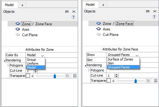
Figure 1: Left: the “Zone” object is active, with rendering options shown in the “Attributes” section; Right: the “Zone Faces” object is active, with the rendering options shown. Clicking on the label allows switching from one to the other.
Show/Hide tools (“Hide”, “Show Selected Only”, “Hide Selection”, “Show All”) facilitate cutting into the model to access interior spaces or reducing the model to exact areas of interest. In addition, “Range” elements may be applied as well. These operate similarly to the “Range” elements that View panes use for plotting. One significant difference is that range elements in the Model pane cannot be combined; they must be specified one element at a time.
Hiding vs. Selection
It is a self-evident but important rule of the interface that an object can only be selected if it is visible: while “zones” are rendered, it is not possible to select “zone faces”; while “zone groups” are set in the “ColorBy” attribute, it is not possible to select by constitutive model assignment, and so on. This applies to all tools in the pane. For instance, when the entire model is visible, the assign groups names to faces automatically tool can quickly return assigned group names to the set of faces that constitute the outer boundaries of the model. However, if the model is reduced—through use of Range elements, for instance—to a much smaller set of visible zones, the assign groups names to faces automatically tool will operate on those zones in exactly the same way (the image below illustrates).
Selection
Selection is performed using the tools provided on the Model pane toolbar. Note the tools provided are contextual to the kind of object currently being rendered/selected (zones or zone faces). Also note that only base operations are described below; however, keyboard modifiers are available to alter/extend tool behavior. See The Model Pane section for detailed usage instructions.
The base select tool ( ![]() ) will select all zones or zone faces of a like color, as determined by the “ColorBy” attribute in the “Objects” control set.
) will select all zones or zone faces of a like color, as determined by the “ColorBy” attribute in the “Objects” control set.
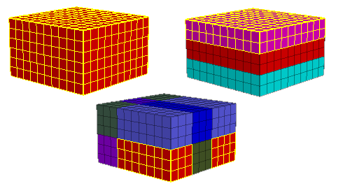
Figure 2: Simple selection by color. Left: ColorBy > Uniform — all zones selected. Middle: ColorBy > Group — zones in the picked group are selected (note these do not need to be contiguous); Right: ColorBy > Model — zones with the same constitutive model assignment are picked. Selection is always indicated with yellow highlighting.
The disambiguate tool ( ![]() ) shows a list of all groups to which the object under the
mouse belongs. “ColorBy” set to “Group” is often the easiest way to select objects, however,
“finding” the desired group to select in models where there are numerous overlapping group
assignments for a given zone (or zone face) can be difficult. This tool provides useful
assistance in that circumstance.
) shows a list of all groups to which the object under the
mouse belongs. “ColorBy” set to “Group” is often the easiest way to select objects, however,
“finding” the desired group to select in models where there are numerous overlapping group
assignments for a given zone (or zone face) can be difficult. This tool provides useful
assistance in that circumstance.
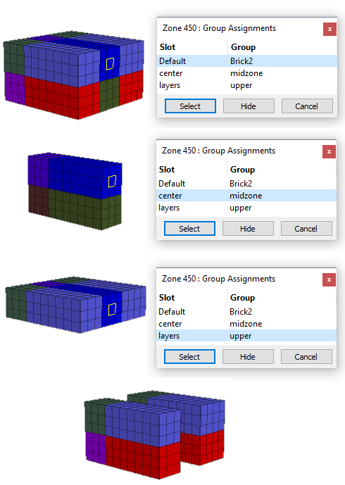
Figure 3: The disambiguate tool is used to show the three groups to which the highlighted zone is assigned. If the “Hide” button is clicked while the “center=midzone” group is highlighted, the result will be as shown in the final image at bottom.
When “zones” are rendered, the assign group names to faces automatically tool (  ) can
be used to “skin” the visible zones into face groups as determined by a break angle. The model
is split into external (and, optionally, internal) face groups at boundaries that are determined
by the break angle (that is, contiguous faces that form angles smaller than the break angle)
plus the current “ColorBy” setting.
) can
be used to “skin” the visible zones into face groups as determined by a break angle. The model
is split into external (and, optionally, internal) face groups at boundaries that are determined
by the break angle (that is, contiguous faces that form angles smaller than the break angle)
plus the current “ColorBy” setting.
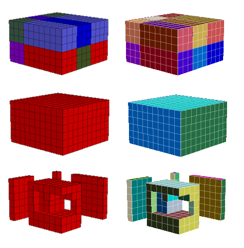
Figure 4: The same operation (Assign Group Names to Faces Automatically) three ways. Top: The model is colored by group, and the face groups that result are shown to the right. Middle: The model is colored uniformly (“uniform”), with resulting face groups shown on the right. Bottom: The model is colored uniformly, and zones have been cut away using the Range and other tools, resulting in the face groups shown on the right.
When “zone faces” are rendered, the select by break angle tool ( ![]() ) is available to
select contiguous faces as single selections (the hide by break angle tool (
) is available to
select contiguous faces as single selections (the hide by break angle tool ( ![]() ) is also
available).
) is also
available).
Selection vs. Hiding
Another interface rule in the Model pane is that selected objects cannot be hidden (this would
be the inverse of the rule that hidden objects cannot be selected). Attempting to use a hide
tool on a selected object will fail (which is indicated in an Information dialog). The one
exception to this is the Hide the Selection tool (  ), which, when pressed, will hide
and de-select whatever is currently selected.
), which, when pressed, will hide
and de-select whatever is currently selected.
Groups
The Assign a Group to the Selection… command (  ) is available on the toolbar to create a group from the current selection. When pressed, it provides a dialog where a group name and, optionally, a slot may be specified (see Groups and Slots and Groups for explanations of groups and slots).
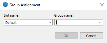
Figure 5: The dialog called when the Assign a Group to the Selection… command is used.
Additional Commands
When “zones” are the currently rendered objects, a Densify the Selected Zones command is available on the command button menu (  ). When zone faces are rendered, a Create a 2D Structural Element command (
  ) is available.
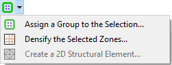
Figure 6: The menu of commands available in the Model pane (zones currently the rendered object).
| Was this helpful? ... | 3DEC © 2019, Itasca | Updated: Feb 25, 2024 |