Creation of Interface Geometry
Interfaces are created with the zone interface create command. For cases in which an interface between two separate grids in the model is required, the zone interface create by-face command should be used to attach an interface to one of the grid surfaces. This command generates interface elements for interface s along all surface zone faces with a center point that fall within a specified range. Any surfaces on which an interface is to be created must be generated initially; it must be possible to specify an existing surface in order to create the interface elements. A gap must be specified between two adjacent surfaces, unless the zone interface create by-face command and the separate keyword are given. In this case, the separate sub-grids may have surface gridpoints at the same location in space.
By default, two interface elements are created for each zone face. The number of interface elements can be increased by using the zone interface s element maximum-edge v command. [1] This causes all interface elements with edge lengths larger than v to subdivide into smaller elements until their lengths are smaller than v. This command can be used to increase the resolution and decrease arching of forces in portions of a model that have large contrasts in zone size across an interface.
Several rules should be followed when using interface elements in FLAC3D:
- If a smaller surface area contacts a larger surface area (e.g., a small block resting on a large block), the interface should be attached to the smaller region.
- If there is a difference in zone density between two adjacent grids, the interface should be attached to the grid with the greater zone density (i.e., the greater number of zones within the same area).
- The size of interface elements should always be equal to or smaller than the target faces with which they will come into contact. If this is not the case, the interface elements should be subdivided into smaller elements.
- Interface elements should be limited to grid surfaces that will actually come into contact with another grid.
A simple example illustrating the procedure for interface creation is provided in “DippingJoint.dat”. The corresponding project file, “DippingJoint.prj”, is located in the folder “datafiles\Interface\DippingJoint.” The example is a block specimen containing a single joint dipping at an angle of 45°.
DippingJoint.dat
model new
model title "Model with a dipping joint"
fish automatic-create off
zone create brick size 3 3 3 ...
        point 0 (0,0,0) point 1 (3,0,0) point 2 (0,3,0) ...
        point 3 (0,0,1.5) point 4 (3,3,0) point 5 (0,3,1.5) ...
        point 6 (3,0,4.5) point 7 (3,3,4.5) ...
        group 'Base'
zone create brick size 3 3 3 ...
        point 0 (0,0,1.5) point 1 (3,0,4.5) point 2 (0,3,1.5) ...
        point 3 (0,0,6) point 4 (3,3,4.5) point 5 (0,3,6) ...
        point 6 (3,0,6) point 7 (3,3,6) ...
        group 'Top'
model save 'int0'
; Create interface elements on the top surface of the base
zone interface 'joint' create by-face separate range group 'Top' group 'Base'
model save 'int1'
Figure 1 shows the grid before the interface is created. Two sub-grid groups are defined: a Base grid and a Top grid. Figure 2 shows the model with the interface elements attached to the Base grid.
A uniaxial compression test with this model is described later in All Properties Have Physical Significance.
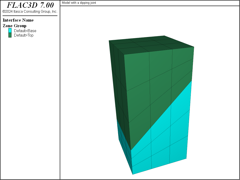
Figure 1: Initial geometry before creation of the interface.
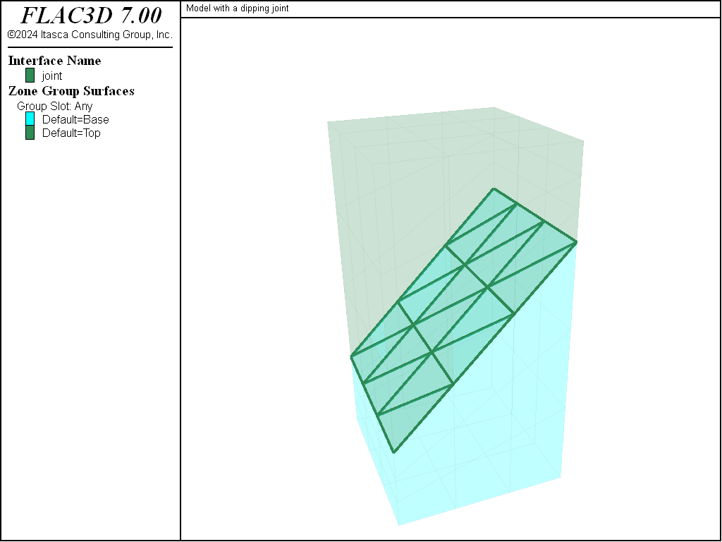
Figure 2: Final geometry.
Endnotes
| [1] | Note that if model configure fluid is invoked, and permeability is on for a particular interface, specifying maximum-edge for that interface will automatically make it impermeable. Do not specify maximum-edge if flow across the interface is desired. |
| Was this helpful? ... | 3DEC © 2019, Itasca | Updated: Feb 25, 2024 |