Formulation
FLAC3D represents interfaces as collections of triangular elements (interface elements), each of which is defined by three nodes (interface nodes). Interface elements can be created at any location in space. Generally, interface elements are attached to a zone surface face; two triangular interface elements are defined for every quadrilateral zone face. Interface nodes are then created automatically at every interface element vertex. When another grid surface comes into contact with an interface element, the contact is detected at the interface node and is characterized by normal and shear stiffnesses, and sliding properties.
Each interface element distributes its area to its nodes in a weighted fashion. Each interface node has an associated representative area. The entire interface is thus divided into active interface nodes representing the total area of the interface. Figure 1 illustrates the relation between interface elements and interface nodes, and the representative area associated with an individual node.
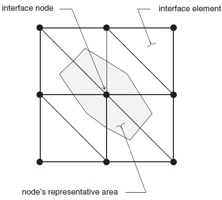
Figure 1: Distribution of representative areas to interface nodes.
It is important to note that interfaces are one-sided in FLAC3D. (This differs from the formulation of two-sided interfaces in two-dimensional FLAC (Itasca 2011).) It may be helpful to think of FLAC3D interfaces as “shrink-wrap” that is stretched over the desired surface, causing the surface to become sensitive to interpenetration with any other face with which it may come into contact.
The fundamental contact relation is defined between the interface node and a zone surface face, also known as the target face. The normal direction of the interface force is determined by the orientation of the target face.
During each timestep, the absolute normal penetration and the relative shear velocity
are calculated for each interface node and its contacting target face. Both of these values are
then used by the interface constitutive model to calculate a normal force and a shear-force
vector. The constitutive model is defined by a linear Coulomb shear-strength criterion that
limits the shear force acting at an interface node, normal and shear stiffnesses, tensile and
shear bond strengths, and a dilation angle that causes an increase in effective normal force on
the target face after the shear-strength limit is reached. By default, pore pressure is used in
the interface effective stress calculation. This option can be activated/deactivated using the
command zone interface effective command by setting effective = on/off.
Figure 2 illustrates the components of the constitutive model acting at interface node (P):
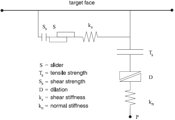
Figure 2: Components of the bonded interface constitutive model.
The normal and shear forces that describe the elastic interface response are determined at calculation time \((t + \Delta t)\) using the relations
| where: | \(F_n^{(t + \Delta t)}\) | is the normal force at time \((t + \Delta t)\) [force]; |
| \(F_{si}^{(t + \Delta t)}\) | is the shear force vector at time \((t + \Delta t)\) [force]; | |
| \(u_n\) | is the absolute normal penetration of the interface node into the target face [displacement]; | |
| \(\Delta u_{si}\) | is the incremental relative shear displacement vector [displacement]; | |
| \(\sigma_n\) | is the additional normal stress added due to interface stress initialization [force/displacement]; | |
| \(k_n\) | is the normal stiffness [stress/displacement]; | |
| \(k_s\) | is the shear stiffness [stress/displacement]; | |
| \(\sigma_{si}\) | is the additional shear stress vector due to interface stress initialization; and | |
| \(A\) | is the representative area associated with the interface node [length2]. |
The inelastic interface logic works in the following way:
Bonded interface — The interface remains elastic if stresses remain below the bond strengths; there is a shear bond strength, as well as a tensile bond strength. The normal bond strength is set using the tension interface property keyword. The command
zone interface nodeproperty shear-bond-ratio = sbr sets the shear bond strength to sbr times the normal bond strength. The default value of property shear-bond-ratio (if not given) is 100.0. The bond breaks if either the shear stress exceeds the shear strength, or the tensile effective normal stress exceeds the normal strength. Note that giving property shear-bond-ratio alone does not cause a bond to be established—the tensile bond strength must also be set.Slip while bonded — An intact bond, by default, prevents all yield behavior (slip and separation). There is an optional property switch (bonded-slip) that causes only separation to be prevented if the bond is intact (but allows shear yield, under the control of the friction and cohesion parameters, using \((F_n)\) as the normal force). The command to allow/disallow slip for a bonded interface segment is
zone interface nodeand by setting bonded-slip on or off.The default state of bonded-slip (if not given) is off.
Coulomb sliding — A bond is either intact or broken. If it is broken, then the behavior of the interface segment is determined by the friction and cohesion (and of course the stiffnesses). This is the default behavior, if bond strengths are not set (zero). A broken bond segment cannot take effective tension (which may occur under compressive normal force, if the pore pressure is greater). The shear force is zero (for a nonbonded segment) if the effective normal force is tensile or zero.
The Coulomb shear-strength criterion limits the shear force by the relation
where:
\(c\) is the cohesion [stress] along the interface;
\(phi\) is the friction angle [degrees] of the interface surface; and
\(p\) is pore pressure (interpolated from the target face) provided the keyword effective = off has not been issued for the interface.
If the criterion is satisfied (i.e., if \(\vert F_s \vert \ge F_{\rm smax}\)), then sliding is assumed to occur, and \(\vert F_s \vert = F_{\rm smax}\), with the direction of shear force preserved.
During sliding, shear displacement may cause an increase in the effective normal stress on the joint, according to the relation
where:
\(\psi\) is the dilation angle [degrees] of the interface surface; and
\(|Fs|_o\) is the magnitude of shear force before the preceding correction is made.
On printout (see the zone interface node list command ) the value of tension
denotes whether a bond is intact or broken (or not set) — nonzero or zero, respectively.
The normal and shear forces calculated at the interface nodes are distributed in equal and opposite directions to both the target face and the face to which the interface node is connected (the host face). Weighting functions are used to distribute the forces to the gridpoints on each face. The interface stiffnesses are added to the accumulated stiffnesses at gridpoints on both sides of the interface in order to maintain numerical stability.
Interface contacts are detected only at interface nodes, and contact forces are transferred only at interface nodes. The stress state associated with a node is assumed to be uniformly distributed over the entire representative area of the node. Interface properties are associated with each node; properties may vary from node to node.
By default, the effect of pore pressure is included in the interface calculation by using
effective stress as the basis for the slip condition. (The interface pore pressure is
interpolated from the target face.) This applies in model configure fluid mode,
or if pore pressures are assigned with the zone water or
zone gridpoint initialize pore-pressure command without specifying
model configure fluid. The user can switch options for interface s by using the
zone interface effective command and by setting effective on or
off. By default in the FLAC3D logic, fluid flow (saturated or unsaturated) is carried
across an interface, provided the interface keyword maximum-edge is not used for that
particular interface. The permeable interface option can be deactivated/reactivated for
interface s by using the zone interface permeability command and by setting
effective on or off. Note that if the keyword maximum-edge is
used after the zone interface element command, and permeability is on
for a particular interface, a warning is issued to inform the user that this interface will be
considered as impermeable to fluid flow. (Note that for fluid flow calculation only, a
mechanical model must be present. Also, the model cycle 0 command with
model mechanical active on should be used to initialize the weighting factors
used to transfer fluid flow information across the interface.) No pressure drop normal to the
joint and no influence of normal displacement on pore pressure is calculated.
Also, flow of fluid along the interface is not modeled.
| Was this helpful? ... | 3DEC © 2019, Itasca | Updated: Feb 25, 2024 |