Object Properties
When you select objects in the construction view, their properties can be edited. If the Object Properties control set is visible in the control panel, you can edit the properties there. Otherwise you can press the [space bar] from the construction view to see the popup property editor. To move from one property to the next in the editor, press Ctrl + ← or Ctrl + → or click the arrows that appear on the top left corner of the editor
The following objects in the construction view can have their properties edited: points, edges, control points, blocks, images and geometric data sets. The images and geometric data sets can have their properties edited in the control panel but not the popup property editor.
Single Point
Figure 1: The popup property editor and control panel for a single point
Coordinates/Position: This is the x and y position of the point. This may be specified with numbers or with FISH variables (note that a single FISH variable can contain a vector and thus be a valid entry for the point position).
Group: One or more points may be grouped together by assigning them to a named group. See the topic Groups for more information.
Edges
Figure 2: The popup property editor and control panel for a selected edge
Edge Type: Specifies one of three types of edge: line, curve, arc. See the topic Curved Edges for information on working with each.
Zones: Specifies the number of zones along an edge. This will override any automatic zoning that has previously been applied to the block that contains the edge.
Ratio: Ratio can be edited when a single edge is selected. It specifies the zoning ratio to use along the edge, where the base setting is 1 (no ratio). Though values may validly range from zero to infinity, most cases should reasonably fall between to .5 to 2.
Group: One or more edges may be grouped together by assigning them to a named group. See the topic Groups for more information.
Blocks
Figure 3: The popup property editor and control panel for blocks
Zone Multiplier: The number of zones specified along the edges of a block will be multiplied by the integer value provided here. See the topic Zoning for more information on methods to control the zoning in a block.
Group: One or more blocks may be grouped together by assigning them to a named group.
Images
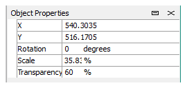
Figure 4: The control panel for images
X and Y: These are the coordinates of the top-left corner of the selected image.
Rotation: This specifies the angle of rotation around the top-left corner of the image. When using the mouse to rotate the image, it will rotate around its center.
Scale: This is a percentage of the original size that the image is scaled to. The image will be scaled using the top-left corner as a reference point.
Transparency: A percentage saying how transparent the image is.
Geometric Data
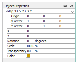
Figure 5: The control panel for imported geometric data
Geometric data can be an imported DXF file, an STL file, or one of Itasca’s .GEOM files.
Map 3D > 2D: When a file of 3D data is imported, you can change its origin and orientation in the display using the controls here.
X and Y: The position of the geometry relative to its origin.
Rotation: Rotation around the center of the geometric data.
Scale: Scale relative to the origin of the geometry.
Transparency: A percentage saying how transparent the data is.
Color: You can change the color used to represent the geometric data by clicking the color control.
| Was this helpful? ... | 3DEC © 2019, Itasca | Updated: Feb 25, 2024 |