Object Selection
The selection tool ( ) is used to select and manipulate objects. When you select an object, you can drag it with the mouse to reposition it and you can edit its properties.
In the construction view, the objects that can be selected include: points (also called nodes), edges, control points, blocks, images and background geometric data.
Appearance
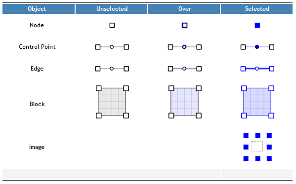
Objects will appear differently depending on their selection state. With the exception of background images and geometry, an unselected object will show highlighting when the mouse gets close enough to click it. When you click the object, it gets drawn in blue to show that it is selected.
For background images and geometry, you can double-click the object to select it, or right-click it to show a context menu with a command for selecting the object. See Background Images / Geometric Data for more information on working with these objects.
The following table shows the states of the different objects.

Multiple Selection and Seed Objects
When selecting multiple objects, only objects of the same type can be selected together. So points could be selected, or edges could be selected, but not points and edges at the same time. This introduces the subject of seed selections. A seed object is the first object to be selected in a multiple selection. It indicates which type of object can be added to the selection.
- There are several ways to accomplish a multiple selection:
- With an object already selected, use the Control key when clicking to add more objects of the same type to the selection. A Control-click can also remove a single object from a selection.
- Drag a selection rectangle (also called a marquee) around the object(s) to be selected. Objects that match the seed type will be selected. If the wrong type of object is selected, simply click an object of the correct type and draw the selection rectangle again.
- Use the command to select all objects of the seed type.
Multiple control points may only be selected on a single edge. Once one control point is selected, only additional control points from the same edge may be added to the selection.
When multiple objects are selected, you can drag any one of the selected objects to move the whole group of objects.
Merging Points
It’s possible to merge 2 points together by dragging one point on top of another point.
Context Menu
In selection mode, depending on where you click in the construction view and whether any objects are selected, different commands may show up in the context menu.
| Add a Point | This command will show the coordinate editor where you can enter coordinates for a new point. |
| Reset View | Sets the view magnification to show the model extent. |
| Zoom to Selection | Sets the view magnification to equal the extent of the current selection. |
| Extrusion Options | Opens the Options dialog to the Extrusion section. |
| Edit Point Properties | Appears when you right-click on a selected point. Shows the coordinate editor for that point. |
| Edit Edge Properties | Appears when you right-click on a selected edge. Shows the property editor for all selected edges. |
| Edit Control Point Coordinates | Appears when you right-click a selected control point. Shows the coordinate editor for all selected control points. |
| Edit Block Properties | Appears when you right-click a selected block. Shows the property editor for all selected blocks. |
| Select Background Image | Appears only if an image has been imported. Selects the image. |
| Select Geometric Data Set | Appears only if a geometric data set has been imported. Selects the data set. |
| Next Mode | With a background image or data set selected, puts the object into the next mode (rotation mode). |
| Exit Mode | With a background image or data set selected, deselects the object and takes it out of resize or rotation mode. |
| Set Pin | With a background image selected, puts the mouse into a mode where you can use the pin to hold a point of the image in place during a resize. |
| Release Pin | Removes the pin from the background image. |
Right Mouse Button in Other Mouse Modes
When the select tool is active, all of the select and move operations described above occur on the left mouse button. When one of the other interactive tools is selected (these being the point-edge tool ( ), the control point tool (
 ), the blocking tool (
 )), all select/move operations described here are available on the right mouse button. This allows you to work with an interactive tool without having to switch repeatedly back and forth from the active tool to the select tool to make position or property adjustments.
| Was this helpful? ... | 3DEC © 2019, Itasca | Updated: Feb 25, 2024 |
