Plastic Hinge Formation in a Shell Structure
Problem Statement
Note
To view this project in FLAC3D, use the menu command . Choose “Structure/Shell/PlasticHinge” and select “PlasticHinge.prj” to load. The main data files used are shown at the end of this example. The remaining data files can be found in the project.
This example demonstrates a procedure by which FLAC3D can be used to calculate the initiation and
subsequent behavior of a plastic hinge line that forms within a shell structure. The double-node
method described in Plastic Hinge Formation in a Beam Structure is replicated
using shell elements. Double nodes are created along the hinge line, and then appropriately link
these nodes together. The double nodes allow a discontinuity in the rotation to occur when the
limiting plastic moment is reached. For shell elements, there is no analog to the single-node
method (using the structure beam property plastic-moment command) that can be used to model
plastic hinges in beam elements.
The problem to be considered is described in Plastic Hinge Formation in a Beam Structure and shown in Figure 1. The FLAC3D model simulates a beam of 10 m length and 1 m depth (see Figure 2). A cross-diagonal mesh pattern is utilized to ensure symmetric response, and a DKT-CST Hybrid Shell Element is utilized to support the membrane loading that will develop after failure if the problem is run in large-strain mode. The Young’s modulus and Poisson’s ratio are set equal to 200 GPa and 0, respectively. The shell thickness is set equal to 0.133887 m to produce a second moment of inertia, \(I\), equal to 200 × 10-6 m4.
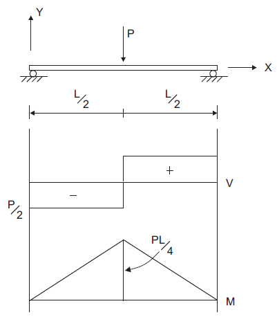
Figure 1: Simple beam with single concentrated load.
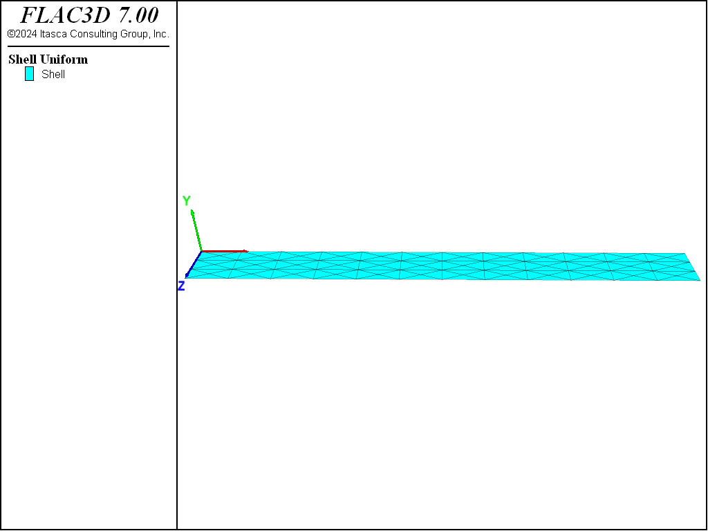
Figure 2: FLAC3D model for plastic hinge example using shell elements.
Two separate structure shell create commands are issued to produce a model containing two
separate shell sections: one for the left half of the beam; the other for the right half of the
beam. Figure 3 shows the shell elements with the node positions
marked; Figure 4 shows an outline of the shell elements, and marks
the location of links. Notice that there is a set of eight nodes that overlap along the beam
center line, which are connected by node-to-node links.
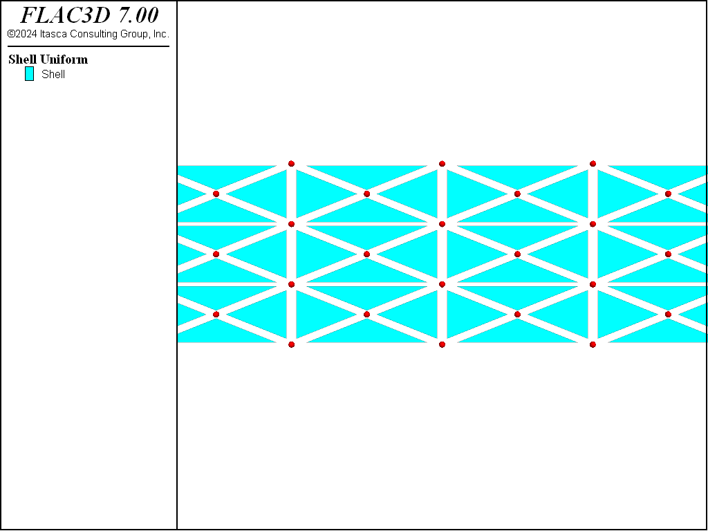
Figure 3: Shell elements—nodes are shown as spheres.

Figure 4: Shell elements—link locations are shown as spheres.
We now create appropriate linkages between these nodes with the commands
struct node join
struct link attach rotation-z=normal-yield ; Change z-rot dof to normal-yield
; Set properties of those springs
struct link property rotation-z area=1.0 stiffness=5e9
struct link property rotation-z yield-compression=8.33e3 yield-tension=8.33e3 range position-x 5.0 position-z 0.3 0.7
struct link property rotation-z yield-compression=4.17e3 yield-tension=4.17e3 range position-x 5.0 position-z 0.0
struct link property rotation-z yield-compression=4.17e3 yield-tension=4.17e3 range position-x 5.0 position-z 1.0
The command creates node-to-node links on each node that lies in the same location as another. The links are shown in Figure 4 and are rigid in all directions by default. The next command affects all links by setting the attachment conditions for the \(z\)-rotational direction to be a normal yield spring. three translational directions and the \(x\)- and \(y\)-rotational directions to be rigid, and specifying a normal-yield spring to be inserted in the \(z\)-rotational direction. The final commands set the properties of these normal-yield springs as follows. We set all areas to unity, and we set both the compressive and tensile yield strengths equal to the desired plastic-moment capacity (based on the tributary length associated with each node). The total plastic-moment capacity is 25 kN-m, so we assign 8.33 kN-m to the two center springs and 4.17 kN-m to the two end springs. Finally, we set the spring stiffness equal to a value that is large enough to make the spring deformation small relative to the shell deformation. We choose a value of 5 × 10⁹, which is approximately the rotational stiffness of the nodes just to the left of the center.
Now that the double-nodes have been appropriately linked to one another, simple supports are specified at the beam ends by restricting translation in the \(y\)-direction. A constant vertical velocity is applied to the four target nodes on the right section, and the moment acting at the centroid of an element near the center is monitored during the calculation to determine when the limiting value is reached.
We find that the limiting value of moment is reached (see Figure 5). Figure 6 shows the value at the beam center is found to be 24.89 kN, which is within 1% of the specified moment capacity. Figure 7 shows that a discontinuity in the displacement has developed.
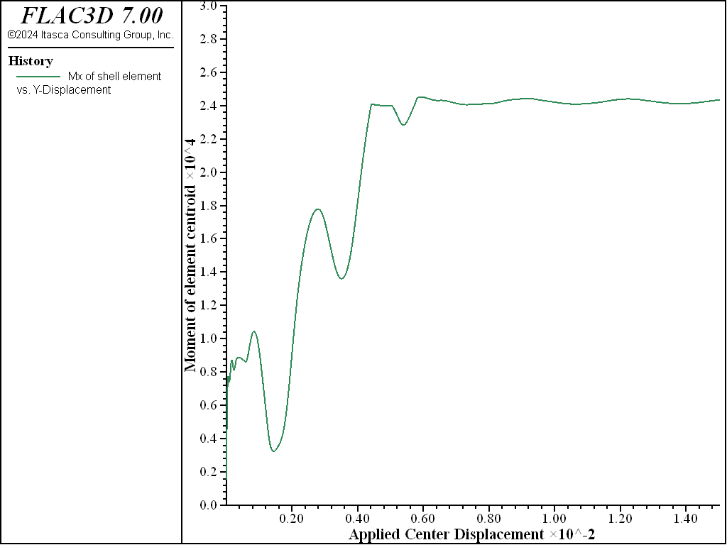
Figure 5: Moment at centroid of an element near the center versus applied center displacement.
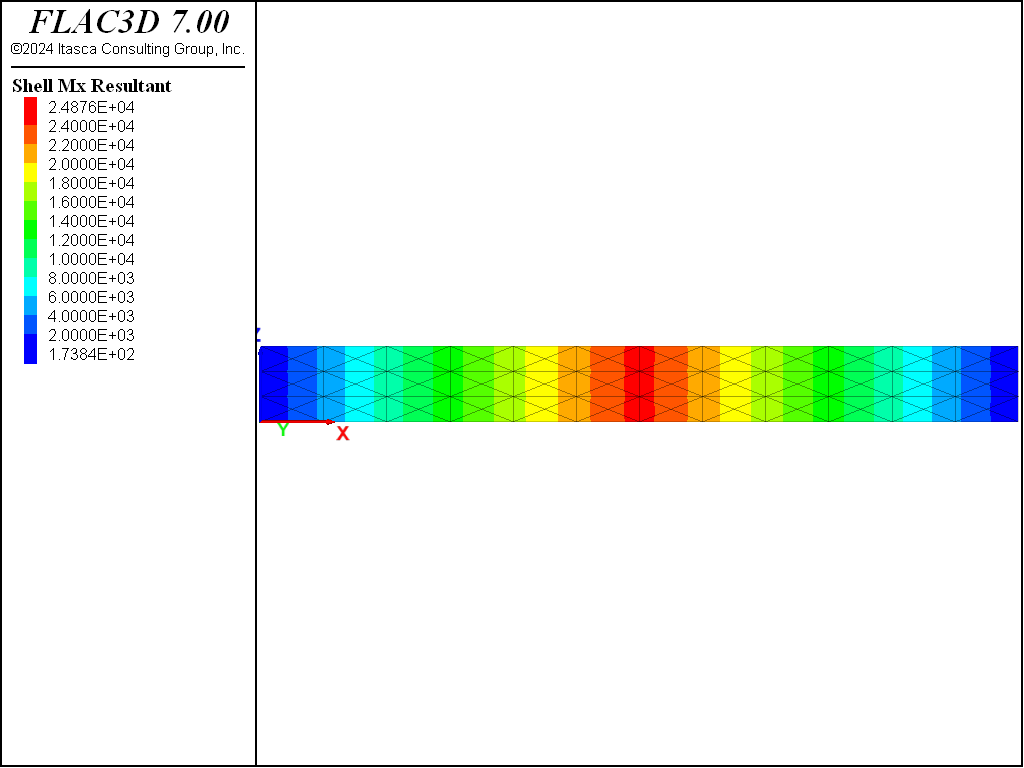
Figure 6: Mx contours on the shell.
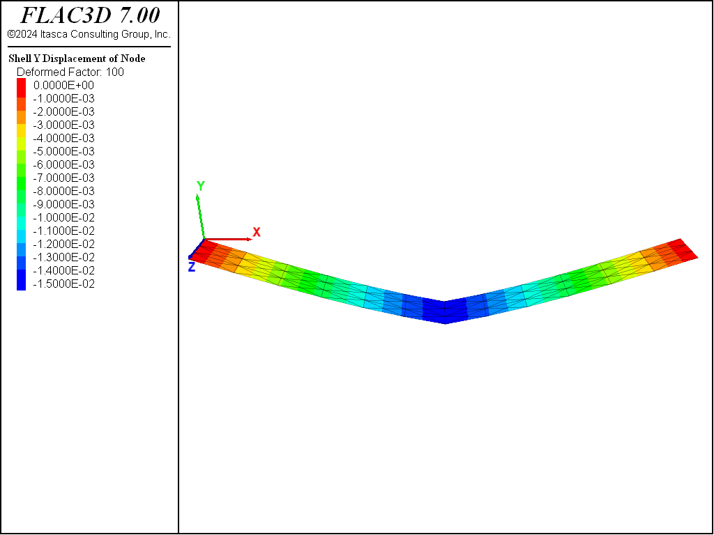
Figure 7: y-displacements on an exaggerated deformation plot of the shell.
Data File
PlasticHinge.dat
model new
model large-strain off
model title 'Plastic hinge formation (double-node method with shell elements)'
; Create shell elements in two groups
struct shell create by-quadrilateral (0,0,0) ( 5,0,0) ( 5,0,1) (0,0,1) ...
                                     size (6,3) id=1 element-type=dkt-csth ...
                                     cross-diagonal group 'Left'
struct shell create by-quadrilateral (5,0,0) (10,0,0) (10,0,1) (5,0,1) ...
                                     size (6,3) id=2 element-type=dkt-csth ...
                                     cross-diagonal group 'Right'
struct shell property isotropic=(2e11, 0.0) thick=0.133887
; Create links (default to rigid in all six dof)
; at nodes whos positions coincide
struct node join
struct link attach rotation-z=normal-yield ; Change z-rot dof to normal-yield
; Set properties of those springs
struct link property rotation-z area=1.0 stiffness=5e9
struct link property rotation-z yield-compression=8.33e3 ...
                     yield-tension=8.33e3 range position-x 5.0 ...
                     position-z 0.3 0.7
struct link property rotation-z yield-compression=4.17e3 ...
                     yield-tension=4.17e3 range position-x 5.0 ...
                     position-z 0.0
struct link property rotation-z yield-compression=4.17e3 ...
                     yield-tension=4.17e3 range position-x 5.0 ...
                     position-z 1.0
; Boundary conditions
struct node fix velocity-y rotation-x rotation-y range position-x= 0.0
                                        ; support at left end - roller
struct node fix velocity-y rotation-x rotation-y range position-x=10.0
                                        ; support at rt. end - roller
struct node fix velocity-z rotation-x rotation-y
                                        ; restrict non-beam deformation modes
struct node fix velocity-y range position-x 5.0 group 'Right'
struct node initialize velocity-y -5e-7 local ...
                       range position-x 5.0 group 'Right'
; Histories
struct node history displacement-y position (5.0,0,0.6667)
struct shell history resultant-mx surface-x 1,0,0 position (4.861,0,0.5)
; Cycle the model
struct damping combined-local
model cycle 30000 ; 0.015 total displacement
model save 'PlasticHinge'
⇐ Cantilever Beam with Applied Moment at Tip — Shell Elements | Isotropic Rectangular Plate with Applied Pressure ⇒
| Was this helpful? ... | FLAC3D © 2019, Itasca | Updated: Feb 25, 2024 |