Interfaces
Often it is necessary in a model to represent planes on which sliding or separation can occur. The classic example is a geologic fault, but this can be also be desired at the boundary between a structure and material like soil.
Where this is necessary, interfaces can be created on zone faces to represent such a fault. Interfaces use a Coulomb sliding with tensile and shear bonding model. While FLAC3D can handle multiple interfaces, if the number or complexity of the surfaces becomes too high, it is recommended that 3DEC be considered instead.
For a complete discussion of FLAC3D interfaces and their most effective use, see Interfaces in FLAC3D Theory and Background. This section will focus on a simple first introduction to interfaces and the issues you need to be most aware of.
Interfaces are most often created with the zone interface create by-face command:
zone interface 'flt' create by-face separate range position-z 5
zone interface node property stiffness-normal 1e8 stiffness-shear 1e8
This command creates an interface named flt by separating all zone faces found at \(z=5\) and placing interface elements and nodes on one side. Contacts are found (and forces generated) by interface nodes coming into contact with zone surface faces that are not part of the interface itself.
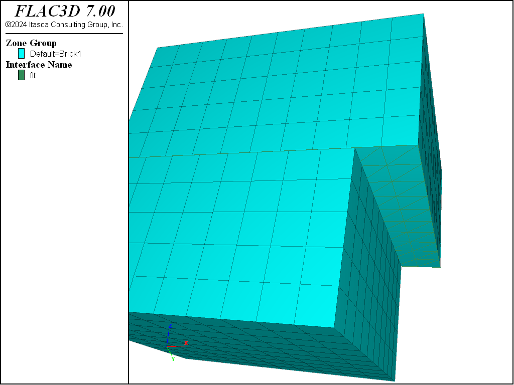
Figure 1: Discontinuity resulting from interface slip.
Every reference to an interface uses a name (like the table command) to indicate which interface is being referred to. An interface will not come into contact with itself, so you cannot necessarily use the same interface name for all contacting surfaces in the model.
You may be familiar with interfaces from FLAC, but the FLAC3D interface logic differs in many respects. There are a few important peculiarities of the FLAC3D interface logic that you must become familiar with.
One Sided
Interfaces in FLAC3D are one-sided objects, unlike the interfaces in FLAC. Interface elements are (in general) created attached to zone surface faces, which in turn create interface nodes. All contact detection is between interface nodes and zone surface faces.
Creating interface elements on only one side of an existing discontinuity in the mesh can sometimes be difficult. When faces are selected using geometric range elements, faces on both sides will fall in the exact same location. If the zones on either side have different group names, then this can be used to select a side. Also, the range orientation range element can be used to select faces with a normal vector in a selected direction.
In the event the discretization on either side of the fault is not the same, interface elements should be applied to the side with the smaller faces.
Most commonly, interfaces need to be created starting with a mesh that is continuous. In that case, it is easiest to separate the mesh and create the interfaces all in one command using the separate keyword (as shown in the example above). The new-side-origin keyword can be used to determine which side of the separation interface elements are applied to. The side opposite the location of the origin will be selected. In the example above, to select the other side, change the command to:
; Create interface
zone interface 'flt' create by-face separate new-side-origin (0,0,10) ...
Absolute Penetration
Unlike almost all other systems in FLAC3D, the calculation of normal stress due to interface penetration is absolute instead of incremental. This means that moving a gridpoint relative to an interface in the normal direction will have an immediate effect on the normal stress calculated. This is not true of accumulated shear stress, which remains incremental.
In small-strain mode, gridpoints do not actually move their location in response to accumulated velocities. Absolute penetration could be determined from the displacement field, but in FLAC3D, displacements are an output value only and can be reset at any time. Therefore, in support of small-strain interfaces, we introduce what is called the “small-displacement” field. This is a vector field that is accumulated from the velocity field every step in small-strain mode only. For the purposes of calculating interface penetration, a gridpoint location is based on the current location plus the small-strain displacement. The small-strain displacement may be initialized using the zone gridpoint initialize displacement-small command, and this is sometimes useful to reset the effective penetration of an interface after some grid motion.
To initialize interface stresses without actually moving gridpoints, we introduce a normal stress increment that is added to the normal stress calculated from absolute penetration. It is this value that is set when the zone interface node initialize-stresses command is given. It can also be set explicitly using zone interface node stress-normal-increment.
Single Target
A given interface node can only be in contact with one target surface face at a time.
For a single fault in a material, one target face per interface node is all that is necessary to accurately model a fault. However, if multiple interfaces intersect, there are not enough contacts per node at the intersection line to resolve the system. See the Interfaces section for further discussion on ways to mitigate this issue. However, in the end, if the exact behavior around multiple intersecting faults is critical to be modeled, it may be better to use 3DEC.
| Was this helpful? ... | FLAC3D © 2019, Itasca | Updated: Feb 25, 2024 |