Pile Structural Elements
Note that pile structural elements are based on the Beam-Type Structural Elements and share the underlying formulation and implementation.
Mechanical Behavior
Each pile structural element is defined by its geometric, material and coupling-spring properties. A pile element is assumed to be a straight segment of uniform, bisymmetrical cross-sectional properties lying between two nodal points. An arbitrarily curved structural pile can be modeled as a curvilinear structure composed of a collection of pile element. The stiffness matrix of a pile element is identical to that of a beam element; however, in addition to providing the structural behavior of a beam (including the ability to specify a limiting plastic moment), both a normal-directed (perpendicular to the pile axis) and a shear-directed (parallel with the pile axis) frictional interaction occurs between the pile and the grid. In this sense, piles offer the combined features of beams and cables. In addition to skin-friction effects, end-bearing effects can also be modeled (see Axially Loaded Pile). Pile elements are suitable for modeling structural-support members, such as foundation piles, for which both normal- and shear-directed frictional interaction with the rock or soil mass occurs. A special material model is also available as an extension to the pile element, to simulate the behavior of rockbolt reinforcement. The model is activated by specifying structure pile property rockbolt-flag on, and includes the ability to account for changes in confining stress around the reinforcement, strain-softening behavior of the material between the pile and the grid, and tensile rupture of the pile.
Each pile element has its own local coordinate system that is described in Beam-Type Coordinate System.
In 3D, The orientation of the node-local system for all nodes used by pile elements is set automatically at the start of a set of cycles (or when the model cycle 0 command is executed), such that the \(x\)-axis is aligned with the average axial direction of all pile elements using the node, and the \(yz\)-axes are arbitrarily oriented in the pile cross-sectional plane.
In 2D, The orientation of the node-local system for all nodes used by pile elements is set automatically at the start of a set of cycles (or when the model cycle 0 command is executed) such that the \(x\) and \(y\)-axes are aligned with the average axial and normal direction of all pile elements using the node, respectively. The orientation of the node-local coordinate system can be modified with the structure node system-local command.
Piles support large-strain sliding (by setting the slide property to on), whereby the interpolation locations (used by the pile nodes to transfer forces and velocities to and from the zones — see Structural-Element Links) will migrate through the grid when running in large-strain mode. This allows one to calculate the large-strain, post-failure behavior of a pile, whereby substantial sliding between the pile nodes and the zones occurs. If a pile node moves out of all zones, then a connection with the zones will not be reestablished if the node is later moved back into zones; however, the connection remains intact as the pile nodes slide between zones.
Piles interact with the grid via shear and normal coupling springs. The coupling springs are nonlinear, spring-slider connectors that transfer forces and motion between the pile and the grid at the pile nodes (by way of the link emanating from each pile node). The behavior of the shear coupling springs is identical to the shear behavior of a grouted cable, as described in Shear Behavior of Grout Annulus. The behavior of the normal coupling springs includes the ability to model load reversal and the formation of a gap between the pile and the grid. The normal coupling springs can simulate the effect of the host medium squeezing around the pile. The formulations for the shear and normal coupling springs and the rockbolt logic are presented in the following three subsections. The behavior is described in terms of the pile element properties listed in Pile Properties (refer to this list for a summary of relevant notations).
Behavior of Shear Coupling Springs
The shear behavior of the pile-grid interface is cohesive and frictional in nature. It is modeled in the same way as the grouted-cable system (described in Shear Behavior of Grout Annulus), in which the grout properties are replaced by the corresponding shear coupling spring properties of (1) stiffness, \(k_s\), (2) cohesive strength, \(c_s\), (3) friction angle, \(\phi_s\), and (4) exposed perimeter, \(p\). The mechanical behavior of the pile in the shear direction is depicted in terms of these parameters, as well as the effective confining stress, \(\sigma_m\) (also defined in Shear Behavior of Grout Annulus), in Figure Figure #pile-shear-material-behavior. Note that the shear coupling spring properties associated with each pile element are averaged at pile nodes.
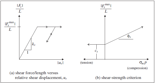
Figure 1: Shear-directional material behavior for pile elements.
Behavior of Normal Coupling Springs
The normal behavior of the pile-grid interface is cohesive and frictional in nature. It is modeled in a fashion similar to the grouted-cable system, and is represented numerically as a spring-slider system located at the nodal points along the pile axis, as shown in Shear Behavior of Grout Annulus. The normal behavior of the pile-grid interface, during relative normal displacement, \(u_n\), between the pile and the host medium (as shown in Figure 2) is described numerically by the normal coupling spring properties of (1) stiffness, \(k_n\), (2) cohesive strength, \(c_n\), (3) friction angle, \(\phi_n\), (4) exposed perimeter, \(p\), and (5) gap-use flag, \(g\). The mechanical behavior of the pile in the normal direction is depicted in terms of these parameters, as well as the effective confining stress, \(\sigma_m\) (defined in Shear Behavior of Grout Annulus), in Figure 3. Note that the normal coupling spring properties associated with each pile element are averaged at pile nodes.
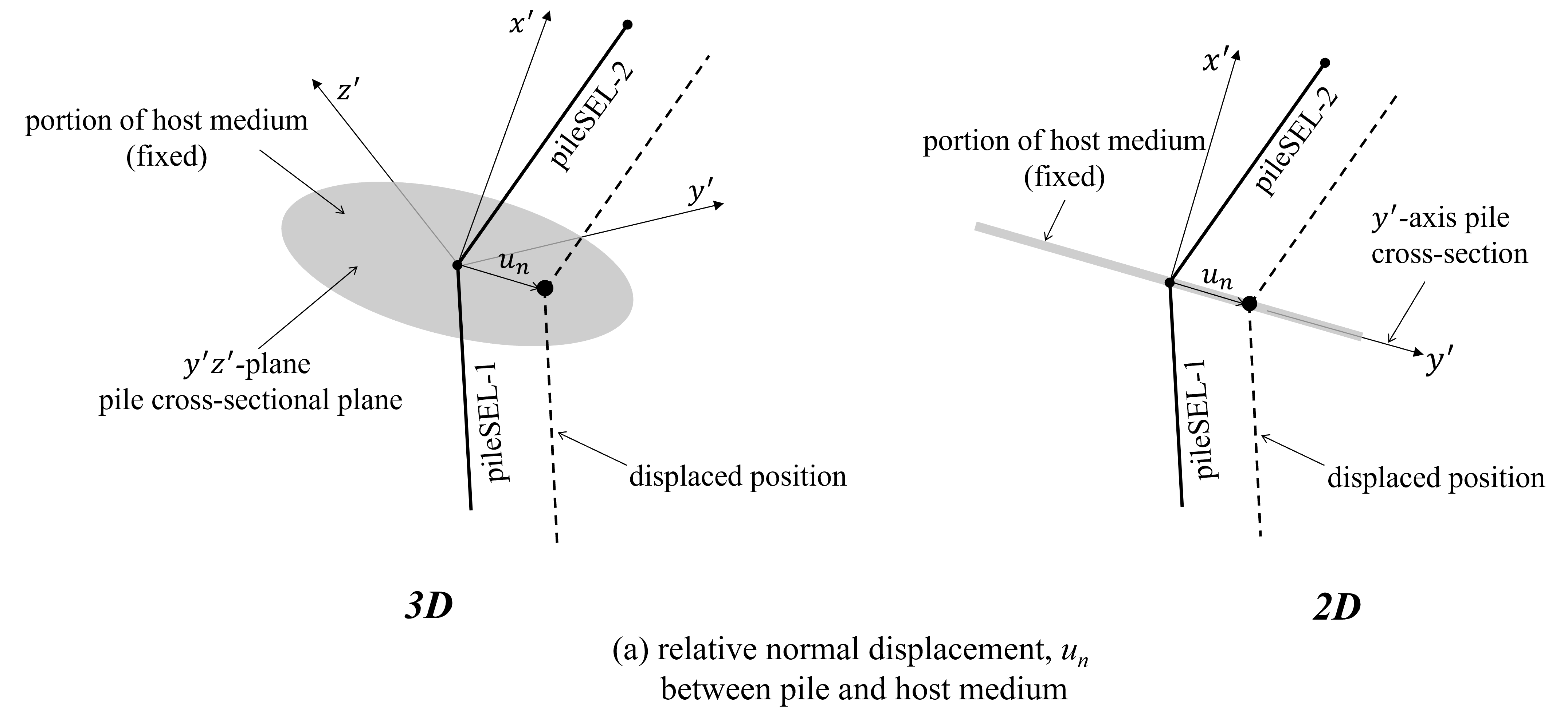
Figure 2: Idealization of normal-directional behavior of pile elements.
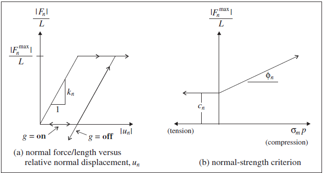
Figure 3: Normal-directional material behavior for pile elements.
When a pile is loaded laterally, a gap may open between the pile and the host medium. If the load is reversed, the pile first must traverse this gap before it can load the host medium on the opposite side. The effect of a gap is considered by setting the gap-use flag to on. In the current implementation of gap behavior, two gap values are stored for each of the two normal directions of the link emanating from each pile node. The two gap values record positive and negative relative displacements along their corresponding direction. Thus, the “gap” appears as a parallelogram with its sides oriented parallel with the \(y'z'\)-axes of Figure 2. Initially, each pile node has no gap, and the gap grows independently in the two normal directions during relative normal displacements occurring while the maximum normal force is acting. The gap does not close, it only expands. The size of the gap can be accessed via FISH and printed with the structure pile list coupling-yield command.
Rockbolt Behavior
An extension of the pile element logic is available to simulate the behavior of rockbolt reinforcement. The behavior of these elements is similar to the behavior of cable elements, except that they also include bending resistance. By invoking the structure pile property rockbolt-flag on command, the following additional behavior is included in the element.
The pile element itself may yield in the axial direction. The yield strength is specified by the property (tensile-yield).
Rockbolt breakage is simulated based upon a user-defined tensile failure strain (tfstrain). A strain measure, based on adding the axial and bending plastic strains, is evaluated at each pile node. The axial plastic strain, \(\varepsilon^{ax}_{pl}\), is accumulated based on the average strain of pile elements using the node. The bending plastic strain is averaged over the element and then accumulated. The total plastic tensile strain, \(\varepsilon_{pl}\), is then calculated by
\[\varepsilon_{pl} = \Sigma \varepsilon^{ax}_{pl} + \Sigma {d \over 2} {\theta_{pl} \over L}\]where:
\(d\)
=
rockbolt diameter;
\(L\)
=
element length; and
\(\theta\)
=
average angular rotation over the element
If this strain exceeds the limit, tensile-failure-strain, the forces and moment in this element are set to zero, and the element is assumed to have failed.
The effective confining stress acting on the pile element is based on the change in stress since installation. Stresses in the grid around the element are stored when the element is installed and, as calculation progresses, the effective confining stress around the element is calculated as the change in stress from the installation state. (For the default pile element, the effective confining stress is based on the current stress state in the zones surrounding the pile.)
A user-defined table (coupling-friction-table) can be specified to give a correction factor for the effective confining stress, in cases of non-isotropic stress, as a function of a deviatoric stress ratio. By default, the confining stress acting on piles is given by the confining stress relation. By specifying a table with coupling-friction-table and setting the coupling-confining-flag flag, factors are applied to the value of \(\sigma_m\) to account for non-isotropic stresses.
Softening as a function of shear displacement for the shear coupling-spring cohesion and friction angle properties can be prescribed via the user-defined tables coupling-cohesion-table and coupling-friction-table.
Response Quantities
Pile responses include force and moment acting on the pile itself, and stress, displacement and yield state in both the normal and shear coupling springs. Additional coupling-spring information includes the current loading direction, the confining stress and the gap being tracked by the normal springs. The pile responses can be accessed via FISH, and
listed with the
structure pile listcommand,monitored with the
structure pile historycommand, andplotted with the Pile plot item.
The sign convention used to plot force and moment distributions along the pile axis is described in Force-Moment Sign Convention.
Properties
Each pile element has constitutive model properties, 15 beam-type properties, 10 coupling-spring properties and 8 rockbolt properties. The beam-type properties are described in Beam-Type Properties. The coupling-spring properties are listed here, followed by the rockbolt properties.
Coupling-Spring Properties
coupling-cohesion-normal, normal coupling spring cohesion per unit length, \(c_n\) [F/L]
coupling-cohesion-shear, shear coupling spring cohesion per unit length, \(c_s\) [F/L]
coupling-friction-normal, normal coupling spring friction angle, \(\phi_n\) (degrees)
coupling-friction-shear, shear coupling spring friction angle, \(\phi_s\) (degrees)
coupling-gap-normal, normal coupling spring gap-use flag, \(g\) (default: off)
coupling-stiffness-normal, normal coupling spring stiffness per unit length, \(k_n\) [F/L2]
coupling-stiffness-shear, shear coupling spring stiffness per unit length, \(k_s\) [F/L2]
perimeter, exposed perimeter, \(p\) [L]
slide, large-strain sliding flag (default: off)
slide-tolerance, large-strain sliding tolerance
The exposed perimeter of a pile element and the properties of the coupling springs should be chosen to represent the behavior of the pile/medium interface commensurate with the problem being analyzed. For piles in soil, the pile/soil interaction can be expressed in terms of a shear response along the length of the pile shaft as a result of axial loading (e.g., a friction pile), or in terms of a normal response when the direction of loading is perpendicular to the pile axis (e.g., piles used to stabilize a slope).
Pile/soil interaction will depend on whether the pile was driven or cast-in-place. The interaction is expressed in terms of the shear resistance that can develop along the length of the pile. For example, driven friction piles receive most of their support by friction or adhesion from the soil along the pile shaft. A cast-in-place end-bearing pile, on the other hand, receives the majority of its support from soil near the tip of the pile.
In many cases, properties needed to describe the site-specific response of the pile/soil interaction will not be available. However, a reasonable understanding of the soil properties at the site is usually provided from standard in-situ and laboratory tests. In such cases, the pile/soil shear response can be estimated from the soil properties. If the failure associated with the pile/soil response is assumed to occur in the soil, then the lower limits for coupling-friction-shear and coupling-cohesion-shear can be related to the angle of internal friction of the soil (for coupling-friction-shear) and the soil cohesion times the perimeter of the pile (for coupling-cohesion-shear). If failure is assumed to occur at the pile/soil interface, the values for coupling-friction-shear and coupling-cohesion-shear may be reduced to reflect the smoothness of the pile surface.
Rockbolt Properties
If the rockbolt logic is active (structure pile property rockbolt-flag on), then the following 8 properties can also be assigned.
coupling-cohesion-table, name of the table relating cohesion of shear coupling spring to relative shear displacement
coupling-confining-flag, flag to activate incremental confining stress logic (default: off)
coupling-confining-table, name of the table relating effective confining stress factor to deviatoric stress
coupling-friction-table, name of the table relating friction angle of shear coupling spring to relative shear displacement
rockbolt-flag, flag to activate rockbolt logic (default: off)
tensile-failure-strain, tensile failure strain, \(\varepsilon_f\) [-]
yield-compression, compressive yield strength (force units), \(F_c\) [F]
yield-tension, tensile yield strength (force units), \(F_t\) [F]
Examples that illustrate the effect of these properties are given in Simulation of Pull-Tests for Fully Bonded Rock Reinforcement.
FLAC3D Examples
Simple examples are given to illustrate the use of piles. This list is incomplete; a complete list of examples that use pile elements is available in Structural Pile Examples.
FLAC2D Examples
Simple examples are given to illustrate the use of piles.
A complete list of examples that use pile elements is available in Structural Pile Examples.
Commands & FISH
| Was this helpful? ... | Itasca Software © 2024, Itasca | Updated: Nov 12, 2025 |
