Buckling of an Axially Loaded Beam
Problem Statement
Note
To view this project in FLAC2D, use the menu command . The main data files used are shown at the end of this example. The remaining data files can be found in the project.
This example demonstrates the buckling behavior of an axially loaded beam with small initial deflection. The beam rests on a base and is fixed in lateral translation at its ends. A global system of coordinates is defined with the \(y\)-axis pointing upward, oriented along the axis of the beam, and with origin at the base of the beam. The beam initial shape is defined by the equation found in Massonnet (1960):
where \(l\) is beam length, and \(f_0\) is maximum initial deflection.
The additional deflection taken by the beam under an axial load, \(P\), is predicted from linear stability analysis by the equation
where \(P_{cr}\) is the minimum critical load for buckling.
The minimum critical load is defined as
where \(E\) is Young’s modulus, and \(I\) is the moment of inertia for lateral flexion.
The additional deflection at the center of the beam \(f\) is thus
For this example, the beam is 200 m long, and the maximum amplitude of initial deflection is 1 cm (or 0.005% of the beam length). Young’s modulus is 257 MPa, and the moment of inertia for lateral flexion is 5.333 m4. The beam is modeled using 20 elements, translation is fixed in all directions at the base, and in the \(x\)- direction at the top. An axial load is applied in increments at the beam top until the critical load is reached. After each increment, the model is cycled to mechanical equilibrium and the load deflection is recorded in a table.
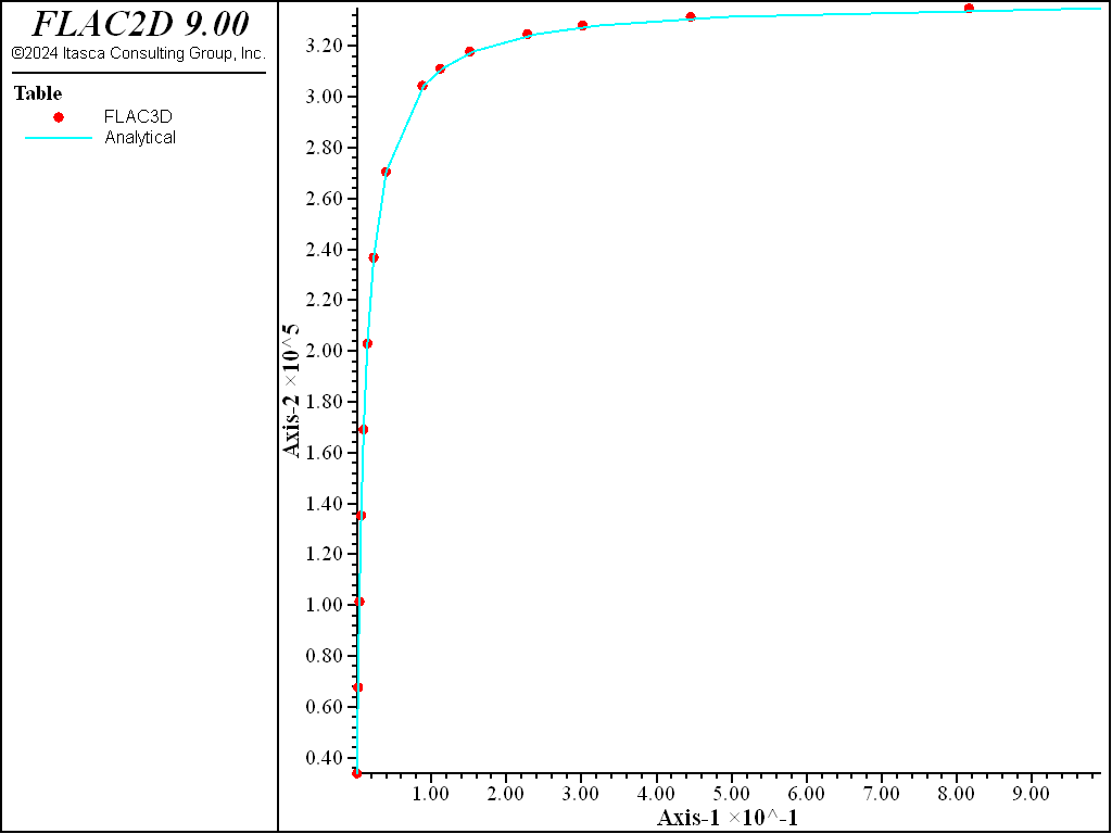
The beam deflection is seen to increase beyond measure as the load converges to the minimum critical value, as expected. A comparison between analytical solution and numerical prediction for additional deflection at the center of the beam is presented in Figure 1. As can be seen, the match between the solutions is very good.

Figure 1: Load deflection curve.
Reference
Massonnet, C. E. Résistance Des Matériaux. Sciences Et Lettres, Liége (1960).
Data File
AxialBuckling.dat
; Axial loading of a beam with small initial deflection.
; Load versus additional deflection at beam half length:
model new
fish automatic-create off
model title "Axial loading of a beam with small initial deflection."
; Create a beam of 20 elements with a sin wave initial deflection in x
fish define createBeam
    local p2 = vector(0,0)
    loop local y (10,200,10)
        local p1 = p2
        p2 = vector(0.01*math.sin(math.pi*y/200.),y)
        command
            structure beam create by-line [p1] [p2] id=1
        end_command
    end_loop
end
[createBeam]

; Setup properties and boundary conditions
model large-strain on
structure beam property young 2.57e8 cross-sectional-area 4 ...
                     direction-y (1,0) moi 5.33 poisson 0.3
structure node fix velocity range position-y 0
structure node fix velocity-x range position-y 200
; create history
structure node history displacement-x position (0,100)
; define loading sequence, in a table as a fraction of the critical load
table 'seq' add (1,.1) (2,.2) (3,.3) (4,.4) (5,.5) (6,.6) (7,.7) (8,.8) ...
                (9,.9) (10,.92) (11,.94) (12,.96) (13,.97) (14,.98) (15,.99)
; Apply Each load in sequence, and record deflection after equilibrium
fish define loadDeflection
    local endNode = struct.node.near(0,200)
    local midNode = struct.node.near(0,100)
    local Pcr = (math.pi/200)^2 * 2.57e8 * 5.333
    loop local i (1,table.size('seq'))
        local load = table('seq',i) * Pcr
        struct.node.apply(endNode,2) = -load
        io.out('Loading step '+string(i))
        command
            model solve convergence 5e-4
        end_command
        local pos = struct.node.pos(midNode)
        pos->y = 0
        local deflect = math.mag(pos) - 0.01
        local x = 0.01/(Pcr/load - 1)
        table('def',deflect) = load
        table('anal',x) = load
        command
            model save ['load'+string(load*100/Pcr)]
        end_command
    end_loop
end
[loadDeflection]
model save 'AxialBuckling'
⇐ Cantilever Beam with Applied Moment at Tip — Beam Elements | Plastic Hinge Formation in a Beam Structure ⇒
| Was this helpful? ... | Itasca Software © 2024, Itasca | Updated: Nov 12, 2025 |
