Elastic Shell (Cylindrical Concrete Vault)
Problem Statement
Note
To view this project in FLAC3D, use the menu command . The main data files used are shown at the end of this example. The remaining data files can be found in the project.
A cylindrical concrete vault supported by two rigid diaphragms and loaded by its own weight is analyzed using the two different shell elements available in FLAC3D. The effects of both element type and mesh pattern on the structural response (deformation and shell stress resultants) are investigated by performing a convergence study, whereby the mesh density is increased. The results quantify the accuracy of the shell elements and illustrate the effects of mesh pattern and mesh density on accuracy. In this problem, there is no coupling between the shell elements and a surrounding continuum, as would be the case in a tunnel analysis. Nevertheless, it is proposed that this problem is similar to such a system, and that the results described here can help guide the selection of the proper discretization and element type in such coupled problems.
This problem has become a de facto standard test problem of a singly curved shell (MacNeil and Harder 1985), and is used as such by Zienkiewicz and Taylor (1991, pp. 123-128) and Carpenter et al. (1986), who refer to it as the Scordelis-Lo roof (Scordelis and Lo 1964). The structure is a cylindrical concrete vault supported by two rigid diaphragms and loaded by its own weight (see Figure 1). Bending action is severe due to supports restraining deflection at the ends, and both bending and membrane deformations contribute significantly to the vertical displacement at the midpoint of the free edge.
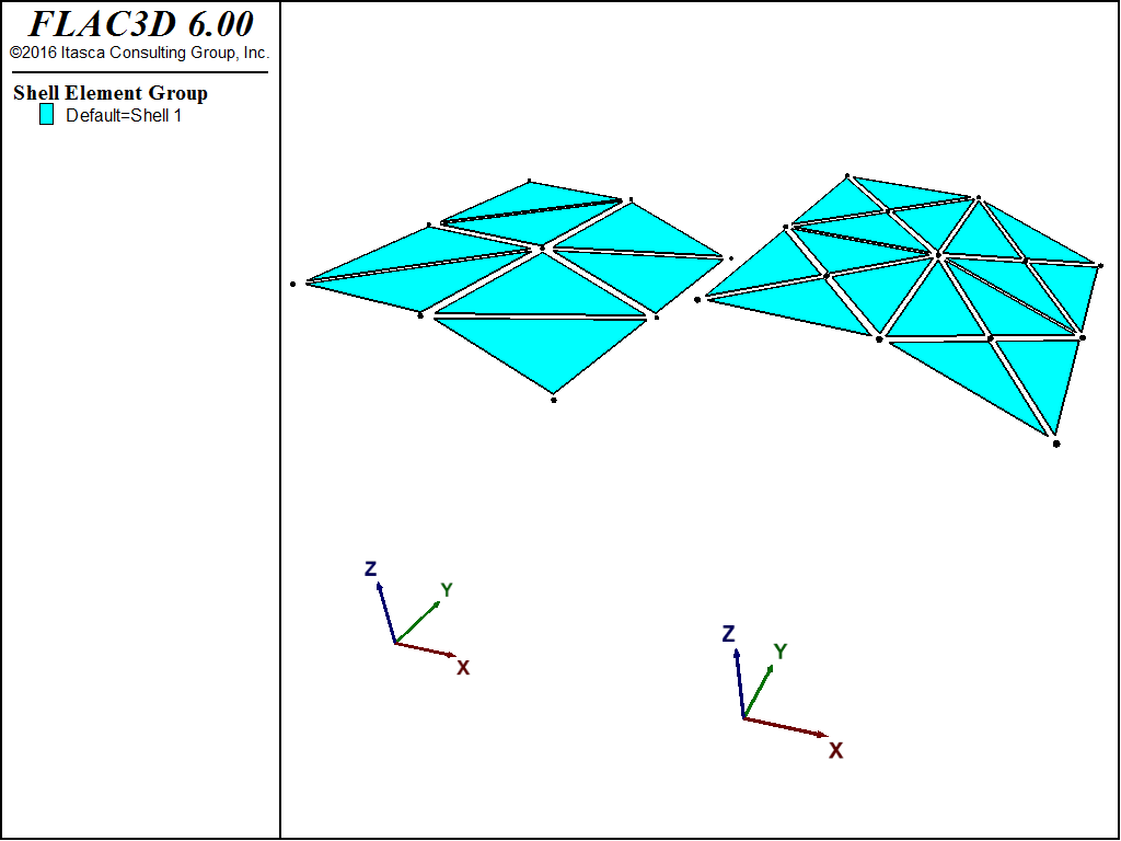
Figure 1: Cylindrical concrete vault supported by two rigid diaphragms.
The vault has a radius of 25 ft, with an included angle of 80°, and a span of 50 ft between the two diaphragm walls. The loading consists of the weight of the concrete shell, which acts in the negative \(z\)-direction. The vault is supported by two rigid diaphragm walls, such that along these two edges (labeled \(A-A'\) and \(B-B'\) in Figure 1), displacements in the plane of each wall are fixed, but the vault is free to move in the \(y\)-direction and to rotate about each edge. (The walls are relatively flexible with respect to loading perpendicular to their surfaces and do not resist bending along their top edges.) The following geometrical and material properties are assigned:
shell thickness |
\(t\) = 3 in |
gravity acceleration |
\(g\) = 32 ft/s2 |
material density |
\(\rho\) = 11.25 lbm/ft3 |
weight of shell |
\(w_s\) = 90 lbf/ft2 |
Young’s modulus |
\(E\) = 4.32 × 10⁸ psf |
Poisson’s ratio |
\(\nu\) = 0.0 |
Closed-Form Solution
Analytical results are presented graphically by Zienkiewicz and Taylor (1991, pp. 123-128) for displacements and moments along various sections of the vault. The results are computed according to an analysis by Scordelis and Lo (1964) and Scordelis (1971). In the present comparison, the graphical plots from Zienkiewicz and Taylor (1991) were utilized. The analytical results include:
the vertical displacement, \(w\), along central section \(C-C'\);
the longitudinal displacement, \(v\), along support section \(A-A'\);
the transverse, \(M_1\), and longitudinal, \(M_2\), moments along central section \(C-C'\); and
the twisting moment, \(M_{12}\), along the support section \(A-A'\).
The vertical displacement at the midpoint of the free edge (at point \(C'\) in Figure 1) used for the present convergence study is taken as 0.3024 ft. MacNeil and Harder (1985) state that 0.3086 ft is the value given by Scordelis and Lo (1964) and that many shell finite-element formulations converge to a slightly smaller value. Both MacNeil and Harder (1985) and Carpenter et al. (1986) use 0.3024 ft for normalization of their results.
FLAC3D Model
The problem has two lines of symmetry, and thus only a quarter of the structure (the shaded area in Figure 1) is analyzed with FLAC3D. A convergence study is performed by increasing the mesh resolution, \(N\), of a set of \(N \times N\) meshes using both crosshatch and cross-diagonal mesh patterns (see Figure 2). For the cross-diagonal meshes, the midpoint nodes lie on the plane formed by the four immediately surrounding nodes, not on the true cylinder surface. This produces the same quadrilateral-faceted mesh for both mesh patterns. If the midpoint nodes are placed on the true cylinder surface, then the pyramid-like facets in the mesh reduce the accuracy of the DKT-CST elements more so than that of the DKT-CST Hybrid elements (Carpenter et al. 1986). (If generating cross-diagonal shell meshes with the cross-diagonal keyword of the structure shell create command, then midpoint nodes will be placed at the centroid of the four corner points of the zone face to which the element is being attached. This produces the desired quadrilateral-faceted mesh.)
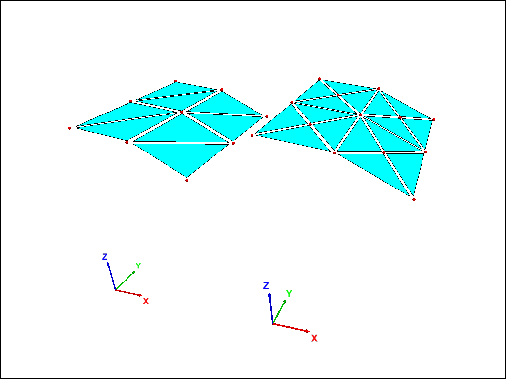
Figure 2: Example of 2 × 2 meshes with crosshatch (left) and cross-diagonal (right) mesh patterns.
The displacement boundary conditions along the four edges of the FLAC3D model are specified in terms of the global coordinate system in Figure 1, as follows. Only fully fixed displacement components are specified; all other displacement components are free.
edge \(A-A'\) : \(u = w = 0\)
edge \(A'-B'\) : all displacement components are free
edge \(C-C'\) : symmetry plane, \(v=0\), \(\theta_x=\theta_z=0\)
edge \(D-D'\) : symmetry plane, \(u=0\), \(\theta_y=\theta_z=0\)
Each mesh is generated using geometry generate commands to first generate the cylindrical shell shape. Then the shell elements are created using the structure shell import from-geometry command. Model construction is completed by specifying material properties (for each shell element), boundary conditions (for each node), and loading. The loading consists of gravity-induced body forces acting in the negative \(z\)-direction, and is assigned by specifying the appropriate element density and a gravity vector. The body forces are computed based on the element volume, and distributed equally to the three nodes of each element.
The data file “CylindricalConcreteVault.dat” loads the data files “store_results.dat” and “run_all_cases.dat”. It then calls the FISH function run_all_cases to solve all 24 cases being examined. Six different discretizations each using DKT-CST and DKT-CSTH elements, with a hatch and a cross-diagonal element pattern. The problems are run to static equilibrium using the model solve command with a ratio-local of 1 × 10⁻⁶.
The moments are recovered in terms of a surface coordinate system oriented such that the \(x\)-axis is equal to the projection of the global \(x\)-axis onto each element surface, and the \(z\)-axis is equal to the direction of each element normal vector. For this convention: (a) the transverse, \(M_1\), and longitudinal, \(M_2\), moments along central section \(C-C'\) correspond with \(M_x\) and \(M_y\), respectively; and (b) the twisting moment, \(M_{12}\), along the support section \(A-A'\) corresponds with \(M_{xy}\).
Results and Discussion
For the convergence study, we vary the element type (DKT-CST and DKT-CST Hybrid) and the mesh pattern (crosshatch and cross-diagonal), while increasing the mesh resolution. We present normalized results for:
the vertical displacement at the midpoint of the free edge (analytical value: -0.3024 ft — see Figure 3);
the transverse moment at the midpoint of the central section \(C-C'\) (analytical value: 2073 ft \(\cdot\) lbf/ft — see Figure 4); and
the twisting moment at the end (point \(A'\)) of the support section \(A-A'\) (analytical value: 1290 ft \(\cdot\) lbf/ft — see Figure 5).
In addition to the convergence results for responses at specific points in the structure, the analytical results along various sections of the vault are compared with the computed results for an 8 × 8 mesh in Figures 6 to 10. These plots provide a general indication of the kind of accuracy one can expect to obtain for a problem in which bending action is severe from the two elements and two mesh patterns available in FLAC3D.
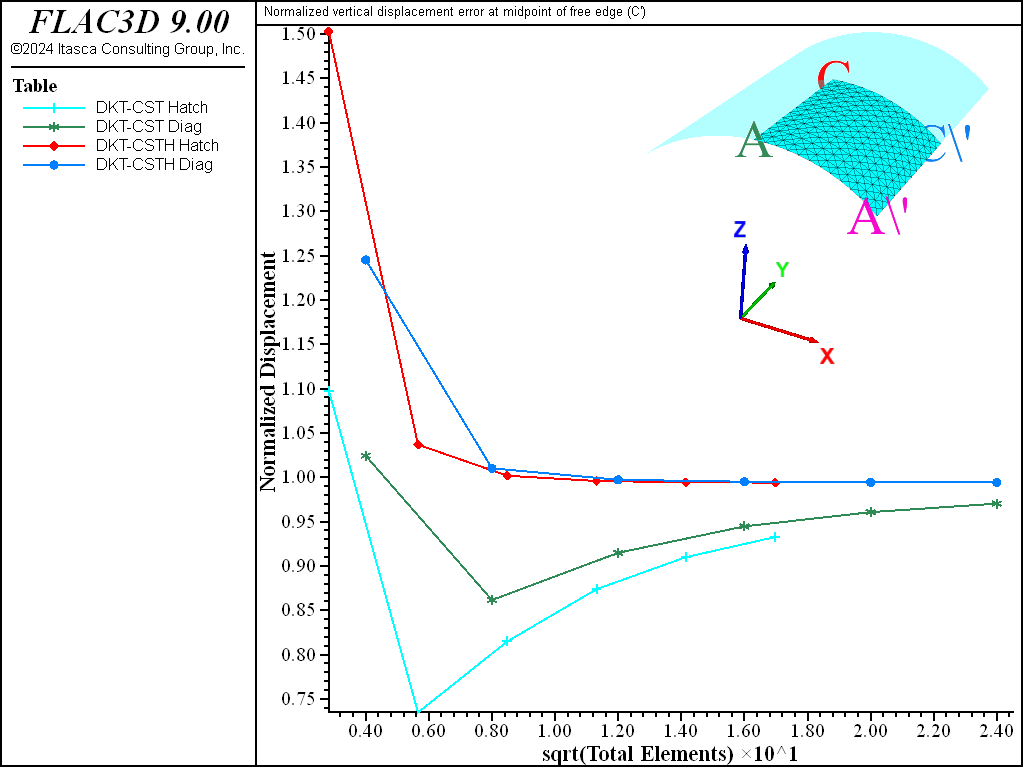
Figure 3: Log of normalized vertical displacement at midpoint of free edge \(C'\).
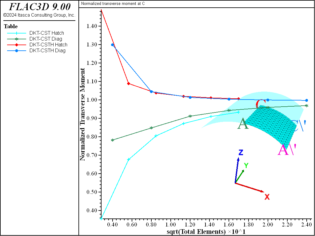
Figure 4: Log of normalized transverse moment at \(C\).
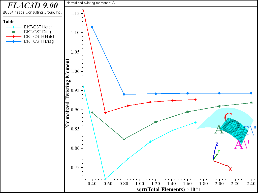
Figure 5: Log of normalized twisting moment at \(A'\).
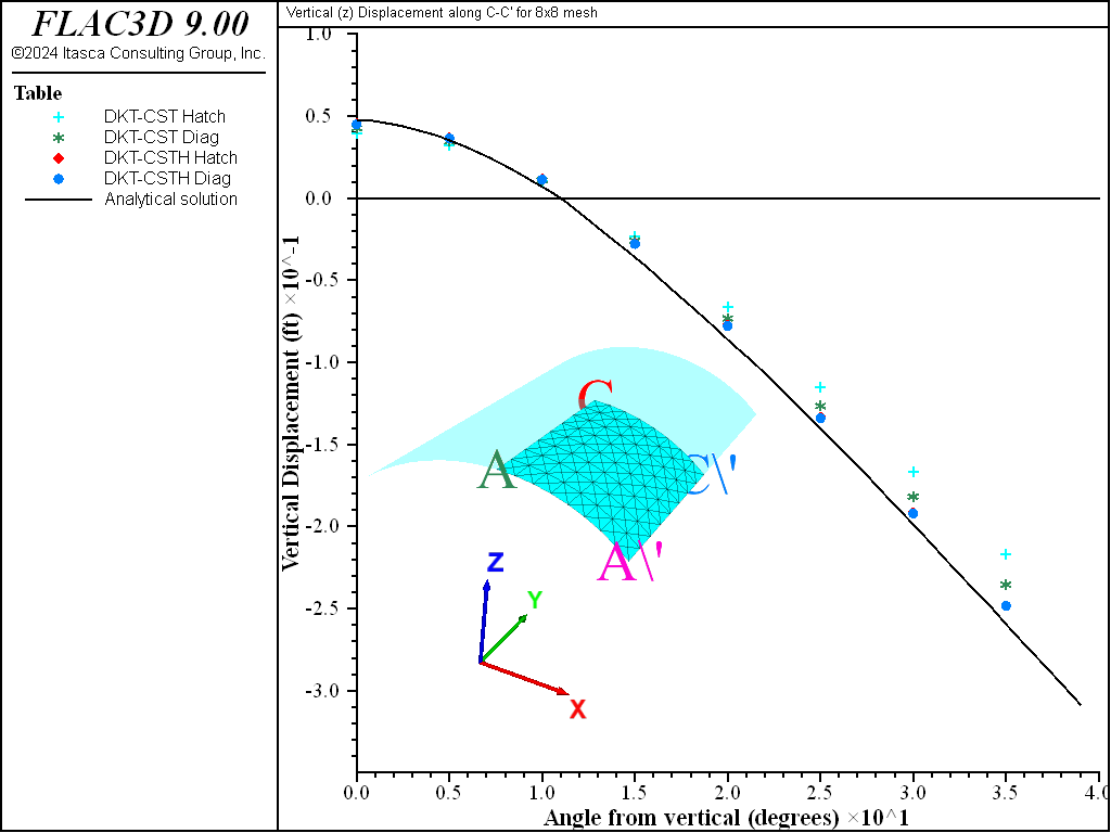
Figure 6: Vertical displacement along central section \(C-C'\) for 8 × 8 mesh.
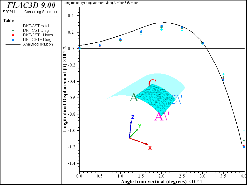
Figure 7: Longitudinal displacement along support section \(A-A'\) for 8 × 8 mesh.
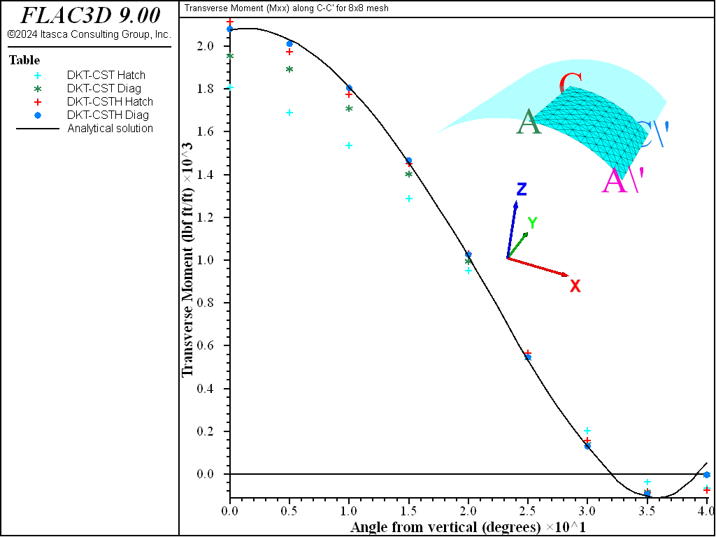
Figure 8: Transverse moment along central section \(C-C'\) for 8 × 8 mesh.
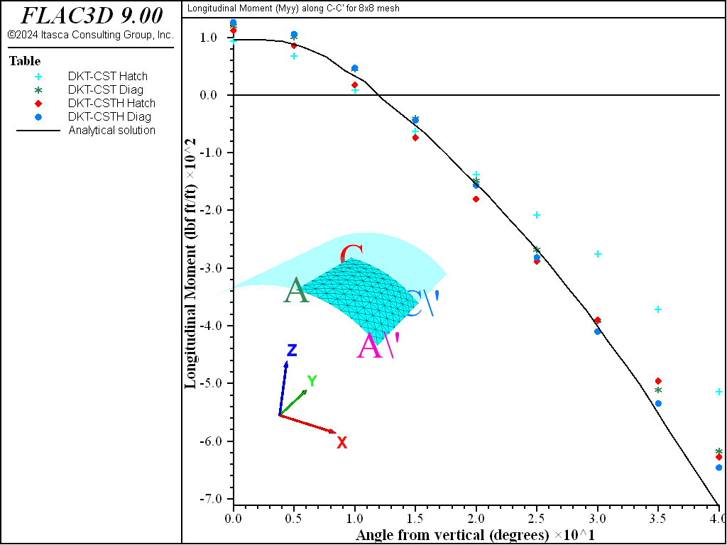
Figure 9: Longitudinal moment along central section \(C-C'\) for 8 × 8 mesh.
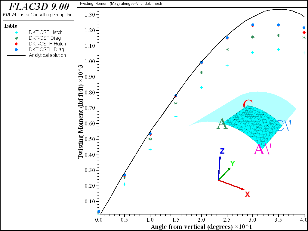
Figure 10: Twisting moment along the support section \(A-A'\) for 8 × 8 mesh.
The results can be summarized and generalized in terms of two statements.
Both the DKT-CST and the DKT-CST Hybrid elements are converging to the analytical displacements and moments. In general, the DKT-CST element is too stiff (displacements and stress resultants are underestimated) and converges more slowly than the DKT-CST Hybrid element. (For a 6 × 6 crosshatch mesh, the DKT-CST Hybrid has converged to a value that is within 0.2% of the analytical displacement, whereas the DKT-CST element is still underestimating this displacement by 18.5%. See Figure 3).
Use of a cross-diagonal mesh softens the DKT-CST element, and therefore improves its performance. The DKT-CST Hybrid element is essentially unaffected by mesh pattern. (This suggests that when using the DKT-CST element, a cross-diagonal mesh should be employed, but when using the DKT-CST Hybrid element, a less costly (fewer nodes and elements) crosshatch mesh can be employed. However, another factor to consider when choosing a mesh pattern is that there is no directional bias in a cross-diagonal mesh, i.e., the response of a shell structure discretized with a crosshatch mesh will differ slightly depending upon the crosshatch direction.)
When using these results as a guide to select the proper discretization of a particular problem, keep in mind that, in this verification problem, the bending action is severe (in particular, there are large membrane-stress gradients). For such problems, the DKT-CST element will be overly stiff, and the DKT-CST Hybrid element will perform better. For problems without large membrane-stress gradients, the performance of the DKT-CST element will be much improved, making it more competitive with the DKT-CST Hybrid element.
References
Carpenter, N., H. Stolarski, and T. Belytschko. “Improvements in 3-Noded Triangular Shell Elements,” International Journal for Numerical Methods in Engineering, 23, 1643-1667 (1986).
MacNeil, R. H., and R. L. Harder. “A Proposed Standard Set of Problems to Test Finite Element Accuracy,” Finite Elements in Analysis and Design, 1, 3-20 (1985).
Scordelis, A. C. “Analysis of Cylindrical Shells and Folded Plates,” in Concrete Thin Shells, American Concrete Institute report SP 28-N (1971).
Scordelis, A. C., and K. S. Lo. “Computer Analysis of Cylindrical Shells,” J. Amer. Concr. Inst., 61, 539-561 (1964).
Zienkiewicz, O. C., and R. L. Taylor. The Finite Element Method. Volume 2: Solid and Fluid Mechanics, Dynamics and Non-linearity, Fourth Edition. London: McGraw-Hill Book Company (1991).
Data Files
CylindricalConcreteVault.dat
model new
fish automatic-create off
; FISH function that creates the mesh
program call 'store_results' suppress ; FISH Stores results in the arrays
program call 'run_all_cases' suppress ; FISH runs all 24 cases 6 sizes,
                                      ;hybrid and not, cross-diagonal and not
structure shell create by-triangle (0,0,0) (1,0,0) (0,0,1) ; Prevent a warning
                                                        ; the first delete
geometry edge create by-positions (0,0,0) (1,0,0) ; Prevent an error
                                            ; the first delete
[run_all_cases]
model save 'final'
run_all_cases.dat
model large-strain off
; Run all 24 cases being examined
; 6 different discretization levels, hybrid vs normal, hatch vs cross-diagonal
fish define run_all_cases
    local etype = map(1,'dkt-cst',2,'dkt-csth')
    local crossd = map(1,false,2,true)
    local clab = map(1,'h',2,'d')
    loop local i (2,12,2)
        loop local h (1,2)
            loop local cd (1,2)
                command
                    ; Delete previous data
                    structure shell delete
                    geometry delete set 'Default'
                    ; Create geometry data in arc at right discretization
                    geometry edge create by-arc origin (0,0,0) ...
                                                start (0,0,25) ...
                                                end (16.06969,0,19.15111) ...
                                                segments [i]
                    geometry generate from-edges extrude (0,25,0) segments [i]
                    ; Create shell elements from geometry
                    structure shell import from-geometry 'Default' ...
                           element-type [etype(h)] cross-diagonal [crossd(cd)]
                    ; Assign properties and gravity
                    structure shell cmodel assign elastic
                    structure shell property young 4.32e8 poisson 0.0 ...
                                          thickness=0.25 density=11.25
                    model gravity 32
                    ; Specify boundary conditions.
                    structure node fix velocity-x velocity-z ...
                           range position-y 0
                    structure node fix velocity-y rotation-x rotation-z ...
                           range position-y 25
                    structure node fix velocity-x rotation-y rotation-z ...
                           range position-x 0
                    ; Solve the model
                    model solve ratio-local 1e-6
                    ; Store the results
                    [store_results(i,h,cd)]
                    ; Save current state for later reference
                    model save [etype(h)+string(i)+clab(cd)]
                endcommand
            endloop
        endloop
    endloop
end

program return
⇐ Elastic Plate with Combined Uniform Lateral and In-Plane Loads | Elastic-Plastic Plate (Collapse Load) with Uniform Lateral Load ⇒
| Was this helpful? ... | Itasca Software © 2024, Itasca | Updated: Nov 12, 2025 |
