Elastic-Plastic Plate (Collapse Load) with Uniform Lateral Load
Problem Statement
Note
There are two projects, each in its own subdirectory. To view them in FLAC3D, use the menu command . Choose “Structure/Shell/CollapseLoads” and select the desired project. The main data files for the square plate are shown at the end of this example.
The collapse load is defined as that value of the load for which the structure remains in equilibrium, but the displacements can increase indefinitely, geometry changes being ignored (Hodge, 1959). The collapse loads for square and circular plates subjected to a slowly increasing uniform lateral load are computed and compared with approximate solutions for simply supported and fixed boundary conditions. This problem quantifies the ability of the DKT element with the von Mises constitutive model to capture the progressive yielding that culminates in the collapse of the plate.
Approximate Solution for Square Plate
An approximate solution for the lower and upper bounds on the collapse load of a square plate loaded by a uniform pressure is given by Hodge and Belytschko (1968). The lower bound problem is formulated as a problem of mathematical programming by using a finite element representation for equilibrium stress fields. The lower bound problem then consists of maximizing the load subject to the constraints imposed by the yield condition, which is satisfied throughout the plate. The upper bound problem is formulated by using a finite element representation for the velocity field. A family of kinematically admissible fields is constructed, and the upper bound problem becomes an unconstrained minimization problem.
The approximate solution corresponds with the following assumptions: (a) the plate is thin such that the displacements caused by transverse-shearing deformations can be neglected; (b) the vertical displacement of the middle surface is small compared to the thickness of the plate (small strain); (c) the plate carries all load in bending — there is no membrane action; and (d) the plate material obeys the von Mises yield condition with no hardening.
The approximate solution for the lower and upper bounds on the collapse load \(\bigl[ p_c^-, p_c^+ \bigr]\) is for the square plate shown in Figure 1. Lower and upper bounds on the collapse load for simple edge support are given by Hodge and Belytschko (1968, Table 1, case 5):
where \(\sigma_Y\) is yield strength, \(t\) is plate thickness, and \(2a\) is side length of the square plate. Lower and upper bounds on the collapse load for built-in edge support are given by Hodge and Belytschko (1968, Table 1, case 11):
The collapse load for the built-in edge support is almost twice as large as that for the simple edge support.
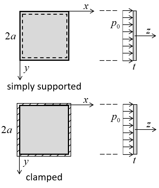
Figure 1: Square plate, lateral loading and coordinate system used to express the approximate solution.
Approximate Solution for Circular Plate
An approximate solution for the collapse load of a circular plate loaded by a uniform pressure is given by Hopkins and Wang (1954). The collapse load is found through integration of an equilibrium equation (a first order, non-linear, ordinary differential equation) between two points (at the plate center and edge) on the yield curve. For the boundary conditions of simple and built-in edge support, it is not possible to derive solutions in simple closed form; however, it is possible to derive approximations (within any desired degree of accuracy) to the exact solutions via numerical integration. Hopkins and Wang (1954) suggest that the following limitations of their analysis need to be borne in mind when comparison is made with experimental results.
The present theory only treats a greatly simplified model of the actual physical problem of the behaviour of a plate under load, because elastic and plastic deformation, and bending and membrane action, all influence in varying degrees the deformation versus load characteristics of the plate. \(\ldots\) If the plate material is non-hardening plastic-elastic, and if membrane action be neglected, then the ultimate load-carrying capacity of the plate is that given by the present theory.
The approximate solution for collapse load corresponds with the following assumptions: (a) the plate is thin such that the displacements caused by transverse-shearing deformations can be neglected; (b) the plate experiences small strain; (c) the plate carries all load in bending — there is no membrane action; (d) the plate consists of perfectly-plastic material that obeys the von Mises yield condition and the associated flow rule; and (e) the plate is entirely plastic when the collapse load is reached.
The approximate solution for the collapse load \(( p_c )\) is for the circular plate shown in Figure 2. The collapse load for simple edge support is given by Hopkins and Wang (1954, Eq. 23):
where \(\sigma_Y\) is yield strength, \(t\) is plate thickness, and \(a\) is radius of the circular plate. The collapse load for built-in edge support is given by Hopkins and Wang (1954, Eq. 41):
The collapse load for the built-in edge support is almost twice as large as that for the simple edge support.
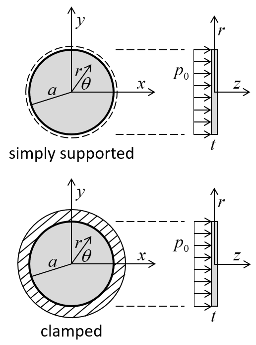
Figure 2: Circular plate, lateral loading and coordinate system used to express the approximate solution.
Particular Problems
The particular problems to be considered are defined as follows. The geometry is defined by the properties:
where \(t\) is plate thickness, and \(2a\) is diameter and side length of the circular and square plates, respectively.
The material is structural steel modeled as a von Mises material with no hardening:
where \(E\) is Young’s modulus; \(\nu\) is Poisson’s ratio; \(\sigma_Y\) is yield strength; and \(H\) is kinematic plastic (hardening) modulus.
For these geometric and material properties, the lower and upper bounds on the collapse loads for the square plate are
and the collapse loads for the circular plate are
FLAC3D Model
The plates are modeled using a mesh of DKT elements as shown in Figures 3 and 4. The approximate solution assumes that the plate carries all load in bending; and thus, the DKT element is used. The von Mises material model is used with nine integration points through the element thickness and three integration points over the element area. The simple edge support case is modeled by a simply-supported boundary condition (translational velocity fixed in the \(z\) direction) for the nodes along the edges. The built-in edge support case is modeled by a clamped boundary condition (translation and rotation fixed in all degrees of freedom) for the nodes along the edges. The uniform lateral load and \(z\)-displacement at the plate center are monitored as histories. Combined damping is used with the default damping factor (see Combined Damping). The model is run in small-strain mode to correspond with the small-strain assumption of the approximate solutions.
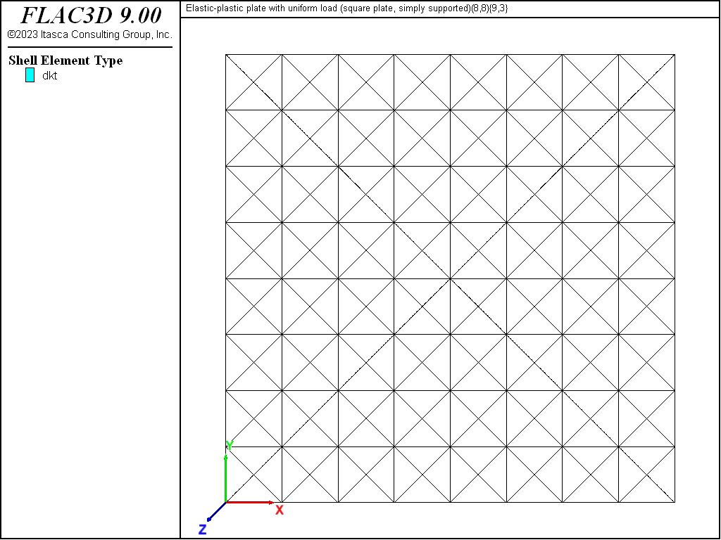
Figure 3: Geometry of the FLAC3D model of the square plate showing mesh and global coordinate system.
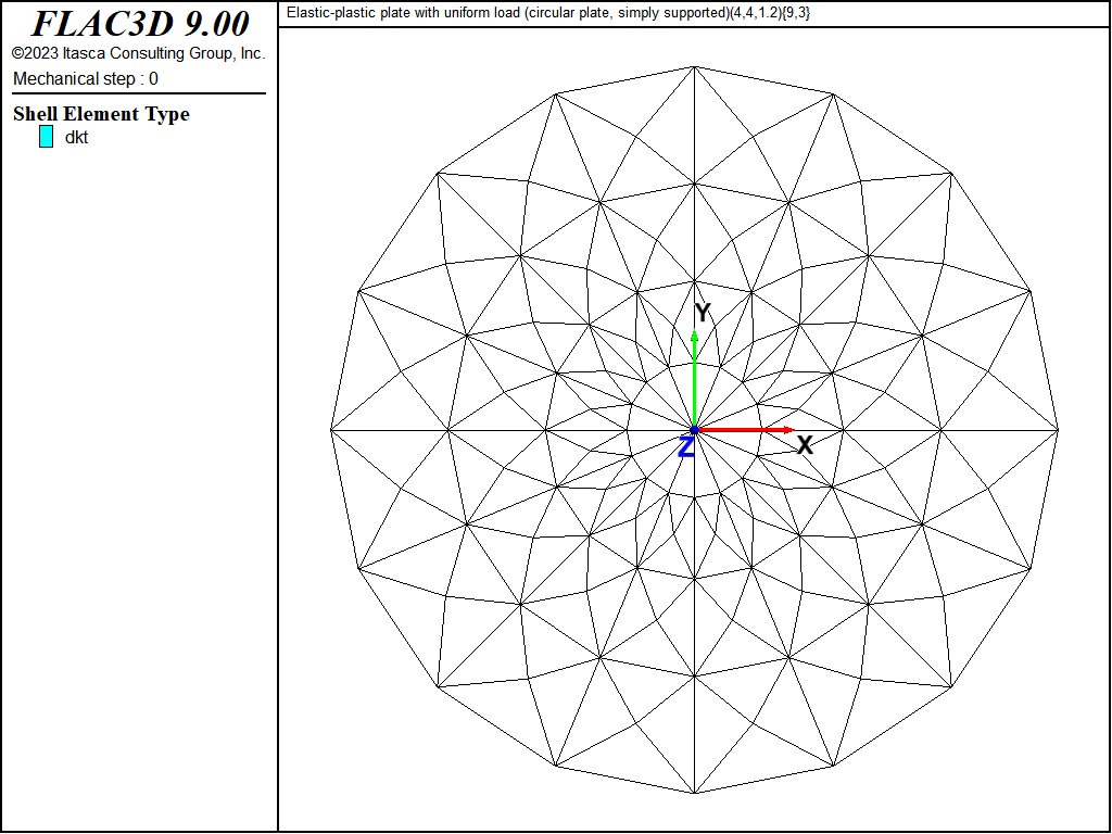
Figure 4: Geometry of the FLAC3D model of the circular plate showing mesh and global coordinate system.
The uniform lateral load is applied incrementally over the plate surfaces as a uniform pressure acting in the positive \(z\) direction. The load is applied incrementally, with the model being cycled until a convergence limit of \(1 \times 10^{-1}\) is achieved after each increment (see Figure 5). The initial load increment is 25 kPa, and the increment reduces to 1 kPa as the collapse load is approached. The collapse load is accurate to 1 kPa, being taken as the load for which the displacements increase indefinitely (indicated by the displacement at the plate center becoming larger than \(a\) — the circular radius or the square half side length).
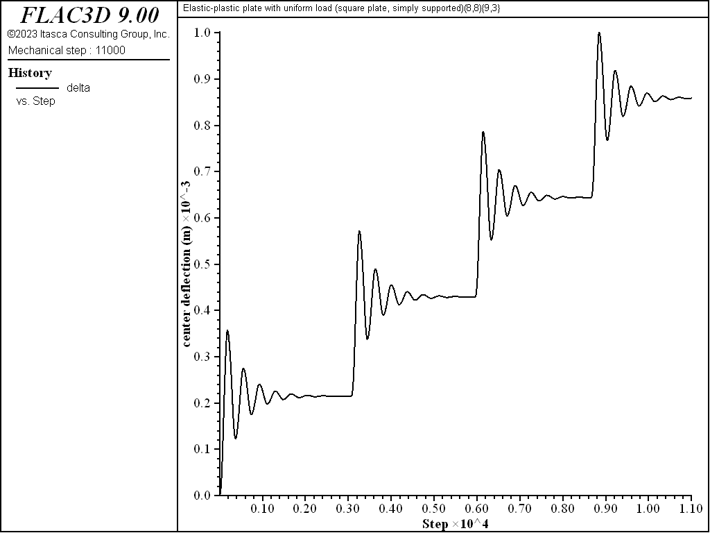
Figure 5: Center deflection of the simply supported square plate during application of the first four 25-kPa load increments.
Results for Square Plate (Simply Supported)
The load-displacement curve and near-collapse yield state for the simply supported square plate is shown in Figure 6. The collapse state is shown in Figure 7, where it is seen that the displacements are increasing indefinitely and eight of the nine integration points through the thickness have yielded (8/9 = 0.89 > 80%) in almost all elements.[1] The yield states are shown by the plot item (see Shell Plasticity Plot Items).
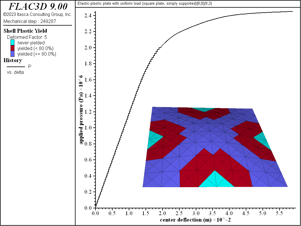
Figure 6: Load-displacement curve and near-collapse yield state (deformation factor: 5) [square plate, simply supported].
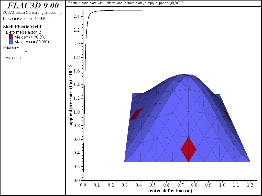
Figure 7: Collapse state (deformation factor: 2) [square plate, simply supported].
The progression of yielding for the simply supported square plate is shown in Figures 8 to 13. Plastification spreads in the plane of the plate as well as through its thickness. The yielding starts at the corners and center. These yielded regions then coalesce into a diagonal shape that expands to encompass nearly the entire plate (see Figure 11). The yielding up to this point is not through the entire thickness. The yielding has progressed through the thickness (eight of the nine integration points have yielded) at the corners and center in Figure 12. This fully yielded region takes on a diagonal shape at the near-collapse load in Figure 13. The progression of yielding compares well with the finite-element results of Wegmuller (1975) shown in Figure 14.
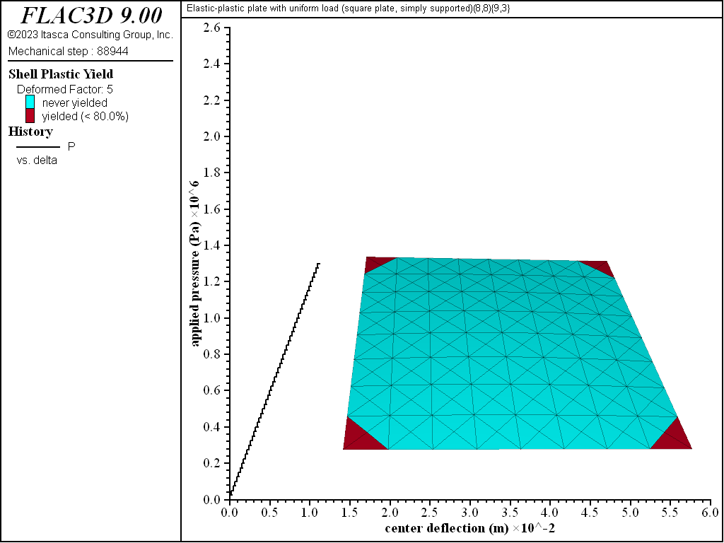
Figure 8: Load-displacement curve and yield state at load of 1300 kPa [square plate, simply supported]
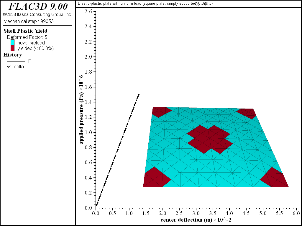
Figure 9: Load-displacement curve and yield state at load of 1500 kPa [square plate, simply supported]
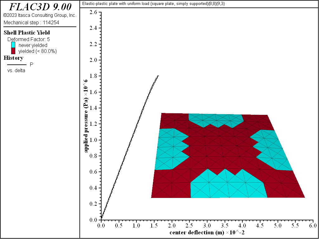
Figure 10: Load-displacement curve and yield state at load of 1800 kPa [square plate, simply supported]
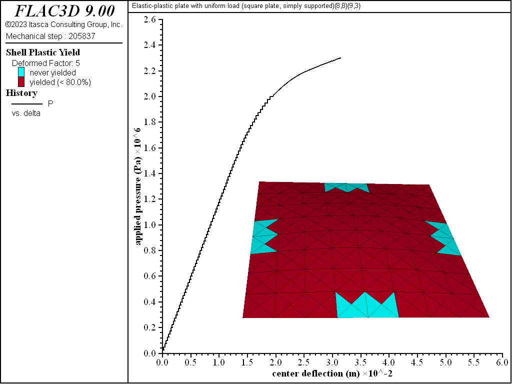
Figure 11: Load-displacement curve and yield state at load of 2300 kPa [square plate, simply supported]
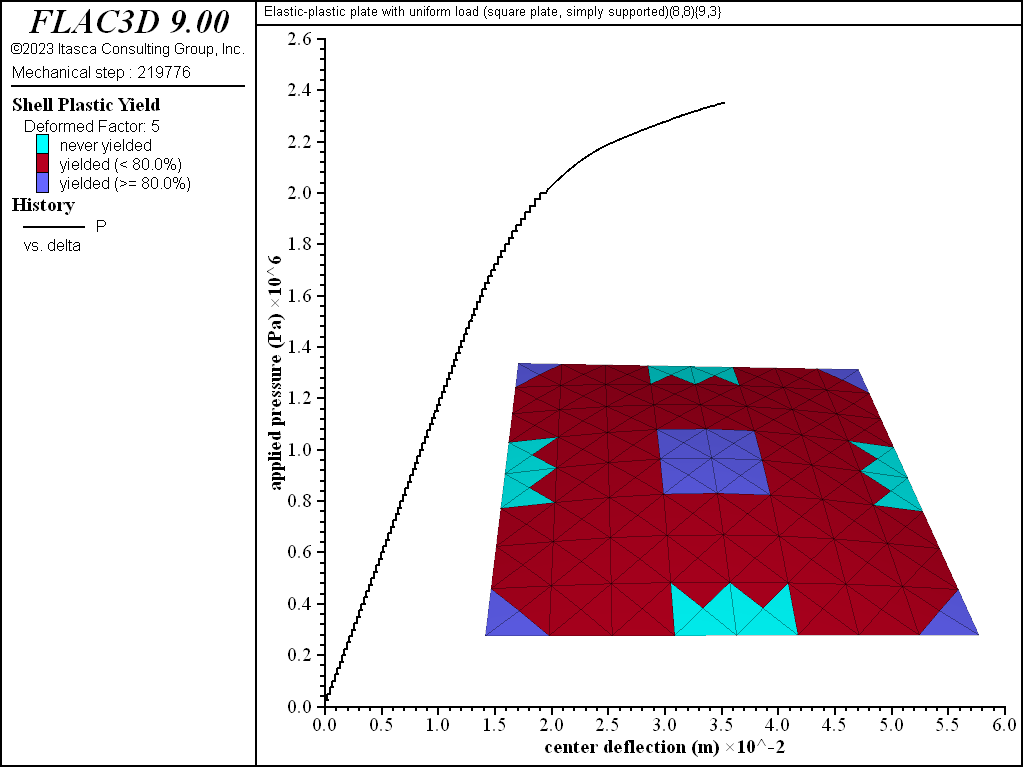
Figure 12: Load-displacement curve and yield state at load of 2350 kPa [square plate, simply supported]
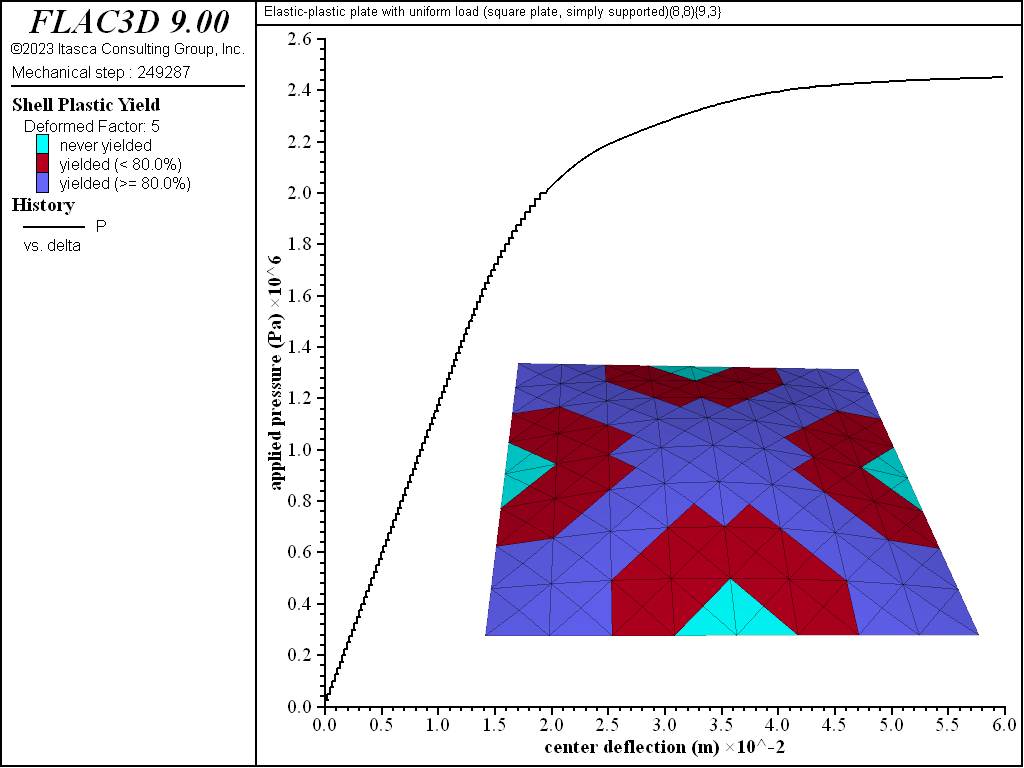
Figure 13: Load-displacement curve and yield state at load of 2450 kPa [square plate, simply supported]
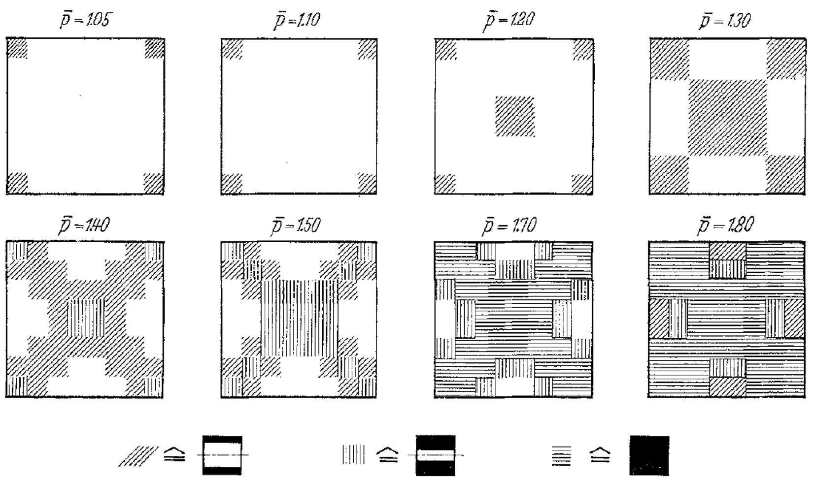
Figure 14: Progression of yielded regions [square plate, simply supported] (From Fig. 10 of Wegmuller[1975])
The effect of number of integration points through the thickness on computed collapse load for the simply supported square plate is shown in Figure 15. The collapse load converges to a value that is between the lower- and upper-bound solutions. The computed collapse load converges from above when using an even number of integration points, and converges from below when using an odd number of integration points.
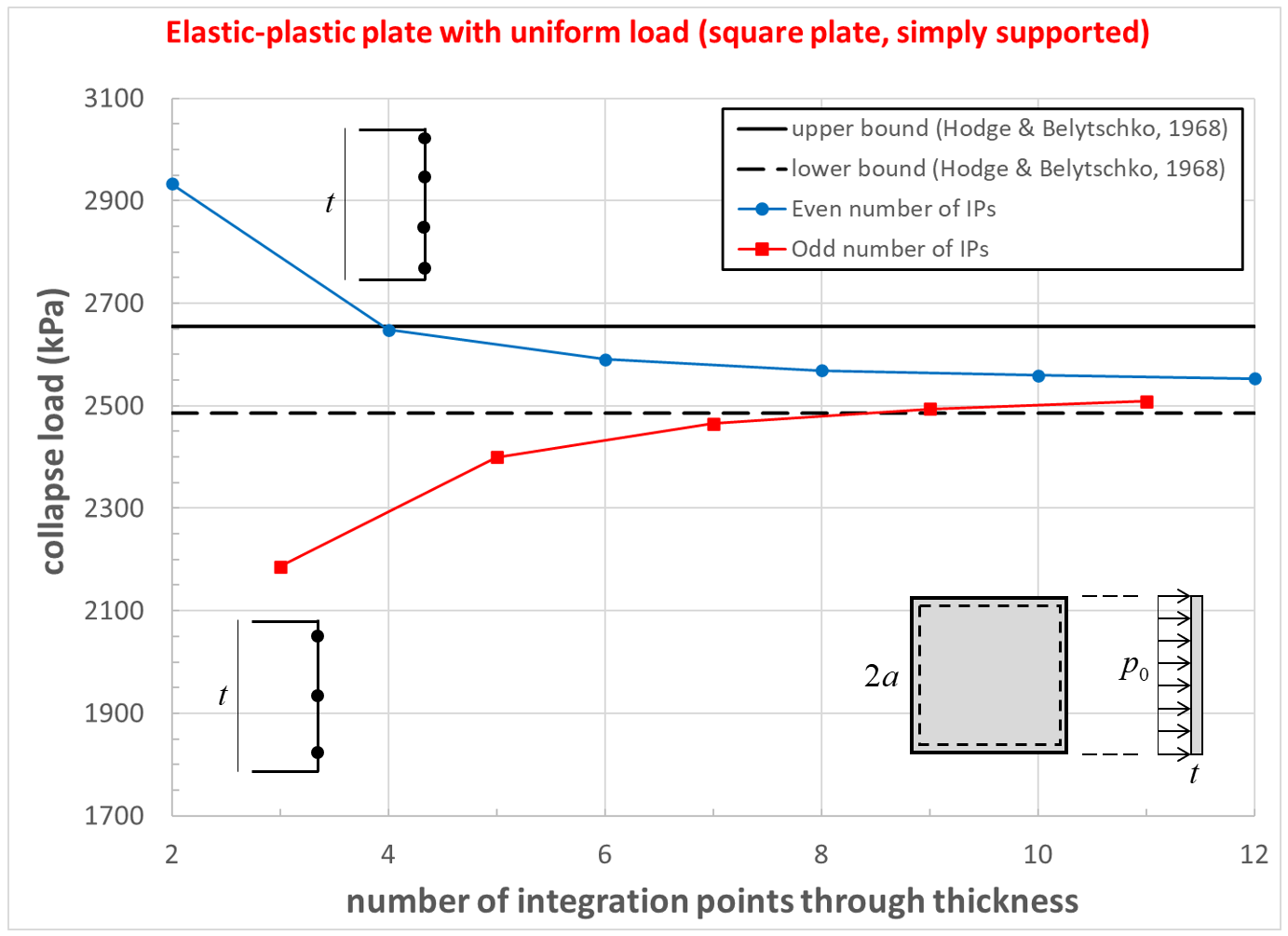
Figure 15: Collapse load convergence study [square plate, simply supported]
Results for Square Plate (Clamped)
The load-displacement curve and near-collapse yield state for the clamped square plate is shown in Figure 16. The effect of number of integration points through the thickness on computed collapse load is shown in Figure 17. The collapse load converges to a value that is between the lower- and upper-bound solutions. The computed collapse load converges from above when using an even numbers of integration points, and converges from below when using an odd numbers of integration points.
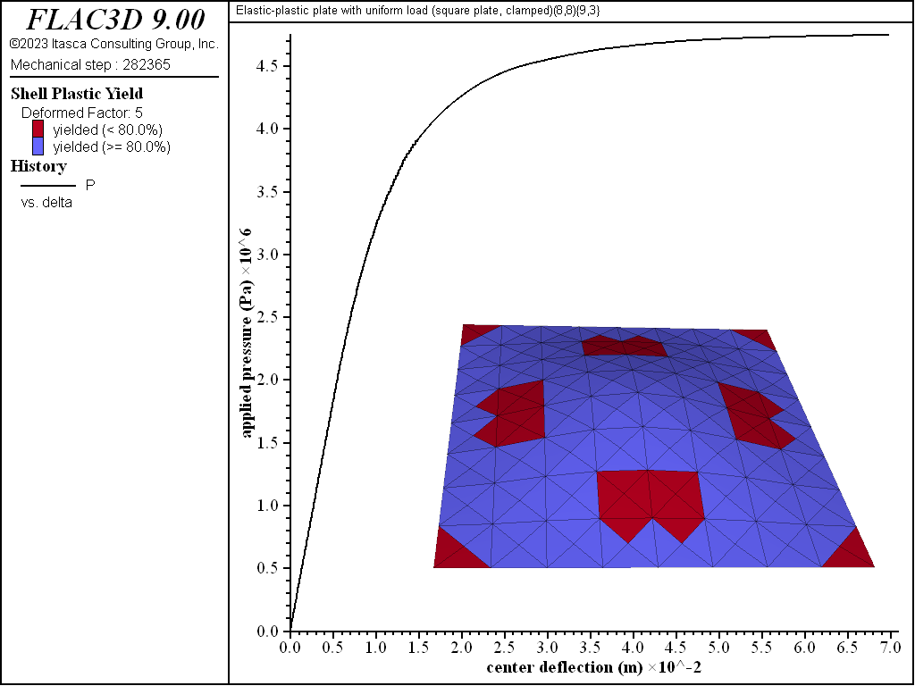
Figure 16: Load-displacement curve and near-collapse yield state (deformation factor: 5) [square plate, clamped].
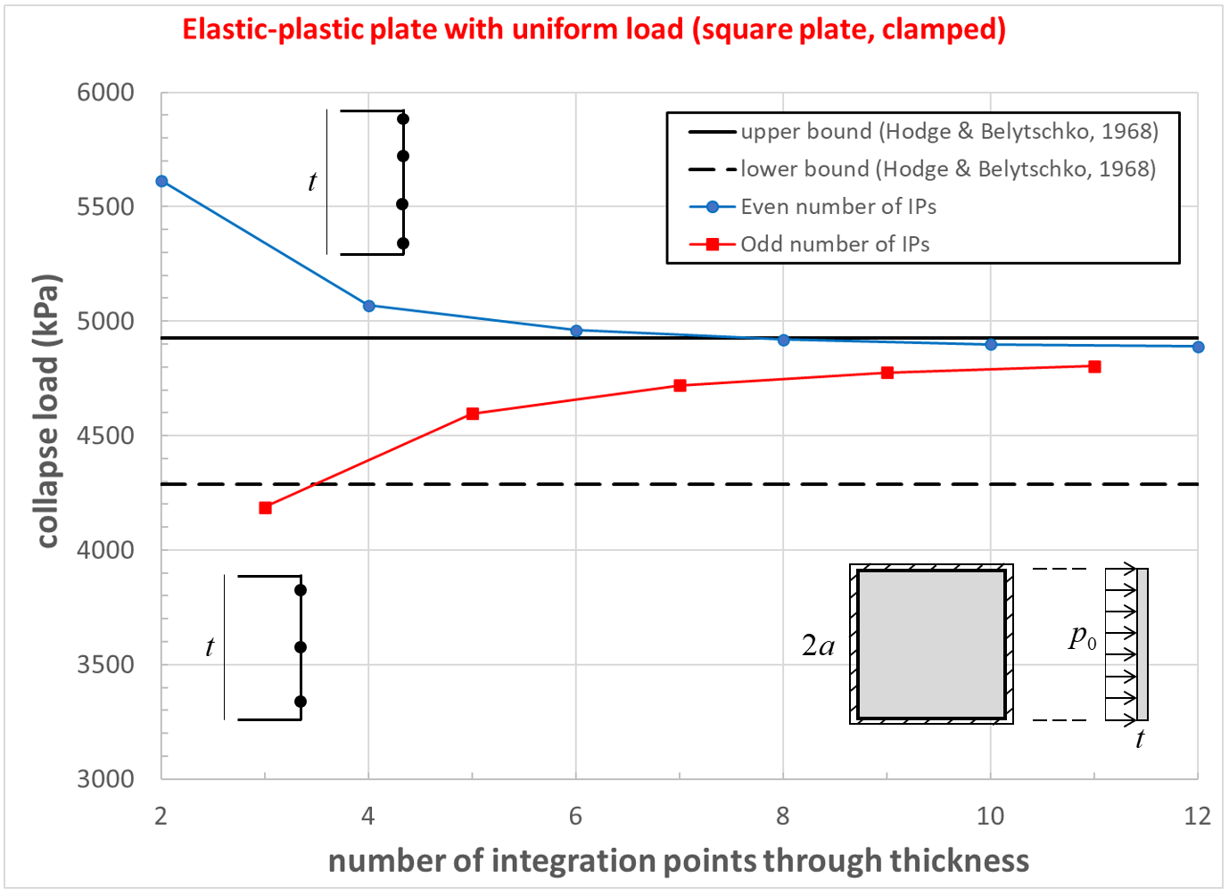
Figure 17: Collapse load convergence study [square plate, clamped]
Results for Circular Plate (Simply Supported)
The load-displacement curve and near-collapse yield state for the simply supported circular plate is shown in Figure 18. Plastification spreads in the plane of the plate as well as through its thickness as shown in Figures 19 to 22. The yielding starts at the center, and spreads to the plate boundary. The yielding at this point is not through the entire thickness. The yielding has progressed through the thickness (eight of the nine integration points have yielded) at the center in Figure 21. This fully yielded region then propagates outward from the center until it reaches the edge, at which point the plate collapses.

Figure 18: Load-displacement curve and near-collapse yield state (deformation factor: 5) [circular plate, simply supported].
Figure 19: Load-displacement curve and yield state at load of 1400 kPa [circular plate, simply supported]
Figure 20: Load-displacement curve and yield state at load of 2200 kPa [circular plate, simply supported]
Figure 21: Load-displacement curve and yield state at load of 2300 kPa [circular plate, simply supported]
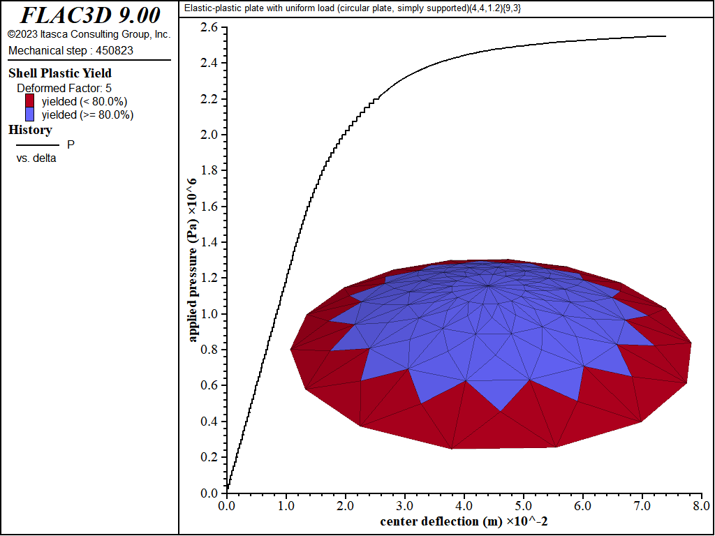
Figure 22: Load-displacement curve and yield state at load of 2550 kPa [circular plate, simply supported]
The effect of number of integration points through the thickness on computed collapse load for the simply supported circular plate is shown in Figure 23. The collapse load converges to the exact solution. The computed collapse load converges from above when using an even number of integration points, and converges from below when using an odd number of integration points.

Figure 23: Collapse load convergence study [circular plate, simply supported]
Results for Circular Plate (Clamped)
The load-displacement curve and near-collapse yield state for the clamped circular plate is shown in Figure 24. The effect of number of integration points through the thickness on computed collapse load is shown in Figure 25. The collapse load converges to a value that is 11 percent larger than the exact solution.[2] The computed collapse load converges from above when using an even number of integration points, and converges from below when using an odd number of integration points.
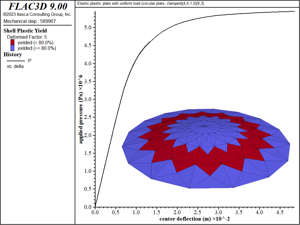
Figure 24: Load-displacement curve and near-collapse yield state (deformation factor: 5) [circular plate, clamped].
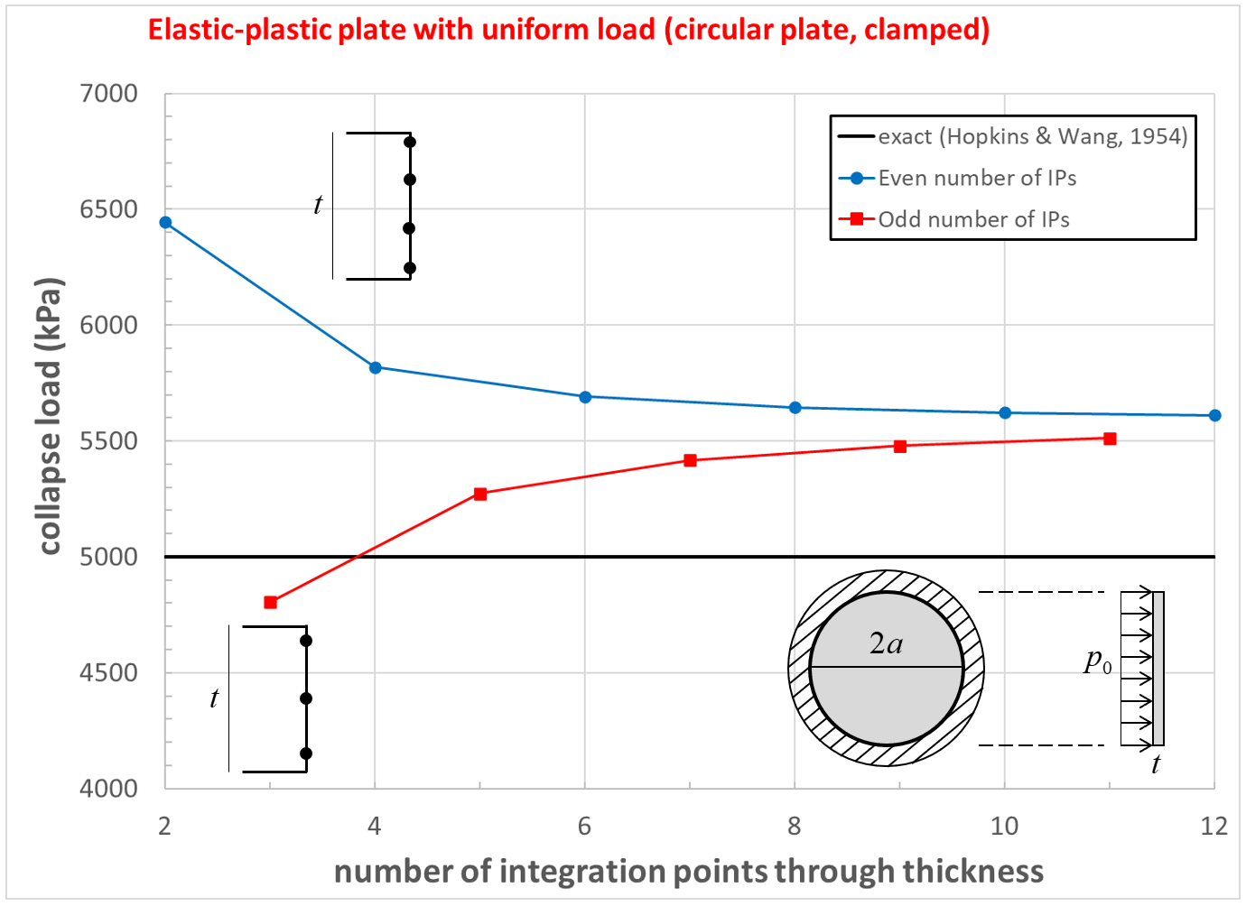
Figure 25: Collapse load convergence study [circular plate, clamped]
References
Hodge, P. G., and T. Belytschko. “Numerical Methods for the Limit Analysis of Plates,” Journal of Applied Mechanics, 35, 796-802 (1968).
Hodge, P. G. Plastic Analysis of Structures, New York: McGraw-Hill Book Company (1959).
Hopkins, H. G., and A. J. Wang. “Load-Carrying Capacities for Circular Plates of Perfectly-Plastic Material with Arbitrary Yield Condition,” Journal of Mechanics and Physics of Solids, 3, 117-129 (1954).
Wegmuller, A. W. “Elastic-Plastic Finite Element Analysis of Plates,” Ingenieur-Archiv, 44, 63-77 (1975).
Endnotes
Data Files
SqPlate.dat
model new ; SQUARE PLATE, SIMPLY SUPPORTED
; Material properties and dimensions (SI units), structural steel
  [E = 200e9]
  [nu = 0.30]
  [sigY = 250e6]
  [t =  100e-3]
  [a = 1250e-3]
; Integration scheme
  [nThick = 9]
  [nArea  = 3]
; Edge condition
  [BCclamped = false]
; Properties of mesh
  [nx = 8]  ; coarse mesh
  [ny = 8]
; =============================================================================
program call 'SqPlates-plastic'

[loadPath(     0, 2000e3, 20,  4, 0.10, 100e3, true)] ; delP=25kPa, save=100kPa
[loadPath(2000e3, 3000e3, 20, 50, 0.10, 100e3, true)] ; delP= 1kPa, save= 50kPa

;##############################################################################
model new ; SQUARE PLATE, CLAMPED
; Material properties and dimensions (SI units), structural steel
  [E = 200e9]
  [nu = 0.30]
  [sigY = 250e6]
  [t =  100e-3]
  [a = 1250e-3]
; Integration scheme
  [nThick = 9]
  [nArea  = 3]
; Edge condition
  [BCclamped = true]
; Properties of mesh
  [nx = 8]  ; coarse mesh
  [ny = 8]
; =============================================================================
program call 'SqPlates-plastic'

[loadPath(     0, 3900e3, 39,  4, 0.10, 100e3, true)] ; delP=25kPa, save=100kPa
[loadPath(3900e3, 5700e3, 36, 50, 0.10, 100e3, true)] ; delP= 1kPa, save= 50kPa

project save

program return
SqPlates-plastic.dat
; Parameters:
;   Material properties and dimensions (SI units) {E, nu, sigY, t, a}
;   Integration scheme {nThick, nArea}
;   Edge condition {BCclamped} : {true, false} = {simply supported, clamped}
;   Properties of mesh {nx, ny}
; =============================================================================
[title_ = 'Elastic-plastic plate with uniform load (square plate']

program call 'loadPath.fis'

fish define setBC
  if BCclamped then
    command
      model title [title_ + ', clamped)']
      structure node fix rotation velocity range group ...
                      'top' group 'bottom' group 'left' group 'right' union
    end_command
  else
    command
      model title [title_ + ', simply supported)']
      structure node fix velocity-z range group ...
                      'top' group 'bottom' group 'left' group 'right' union
    end_command
  end_if
end
[global snCtr]
fish define ctrDeflection
  ctrDeflection = struct.node.disp.global(snCtr)(3)
end
; =============================================================================
; Create mesh, assign shell properties and boundary conditions.
structure shell create by-quadrilateral (0,0,0) ([2.0*a],0,0) ...
                                     ([2.0*a],[2.0*a],0) (0,[2.0*a],0) ...
                    size [nx] [ny] cross-diagonal true element-type dkt
structure node group 'top'    slot 'BCs' range position-y 0.0
structure node group 'bottom' slot 'BCs' range position-y [2.0*a]
structure node group 'left'   slot 'BCs' range position-x 0.0
structure node group 'right'  slot 'BCs' range position-x [2.0*a]
structure shell property thickness [t]
structure shell cmodel assign von-mises
structure shell cmodel plastic-integration [nThick] [nArea]
structure shell property young [E] poisson [nu] ...
                      strength-yield [sigY] modulus-plastic 0.0
[setBC]
structure node history name 'delta' displacement-z position ([a],[a],0)
fish history name 'P' pA
[snCtr = struct.node.near( vector(a,a,0) )]
model large-strain false
structure mechanical damping combined-local

program return
| Was this helpful? ... | Itasca Software © 2024, Itasca | Updated: Nov 12, 2025 |
