zone create command
Syntax
- zone create keyword
Primary keywords:
brick cylindrical-shell cylinder cylindrical-intersection degenerate-brick pyramid radial-brick radial-cylinder radial-tunnel tetrahedron tunnel-intersection uniform-wedge wedge
Create 3D zone-filled primitive shapes (
brick,cylinder, etc.) with a predefined grid pattern.See Primitive-Based Grids for further discussion and examples of the process of creating a mesh using primitive shapes.
To create zones from a 2D cross section that is then extruded into a third dimension, see the
extrudecommand. Also see the i Sketch tool in the user interface along with the commandzone generate from-extruder.To create zones from an interactive assembly of blocks—with control over curved edges—see the
building-blockscommand. Also see the i Building Blocks tool in the user interface along with the commandzone generate from-building-blocks.To create individual gridpoints see
zone gridpoint create.An individual zone may be created with
zone createcommand using thebrickkeyword with thesizeset to (1,1,1).FLAC3D may also read in externally generated grids in several formats, see the
zone importcommand.On meshing with
zone createsee Primitive-Based Grids in Problem Solving with FLAC3D
see Further Discussion: Meshing With Primitives in Tutorial: First FLAC3D Model
Note
Thumbnails of primitives are links (may be clicked) to enlargements that indicate the shapes’ reference points.
For each shape keyword there is a block of modifiers that control its position, shape, and zone distribution. These are marked
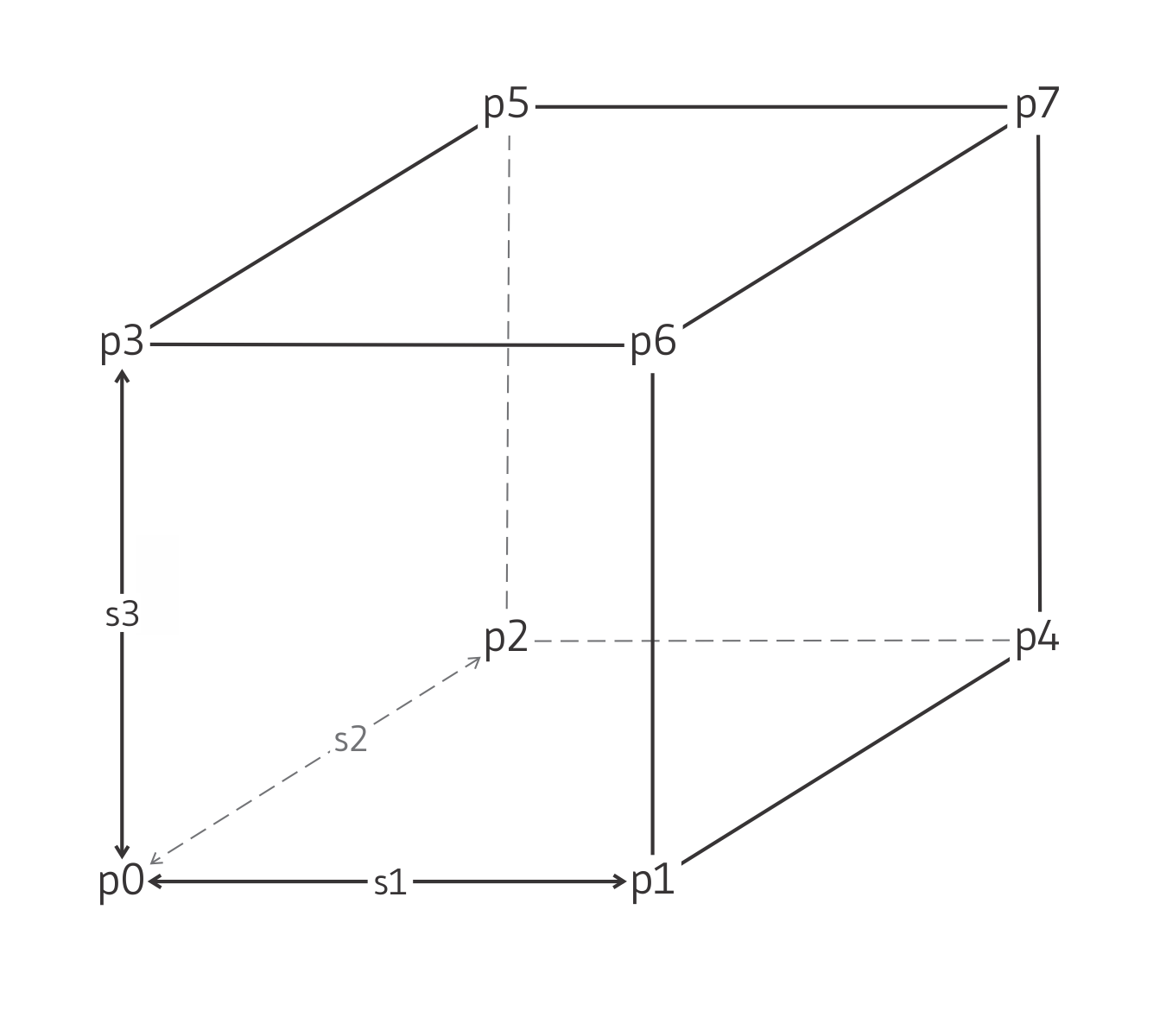
[zonecreateblock]below. Definitions for the keywords in the block are found in the “Keyword Block” section at the end of this page.- brick [zonecreateblock]
Create a hexahedral brick-shaped mesh with eight vertices:

8 reference points, 3 size entries, 0 dimension entries, not
fill-able.
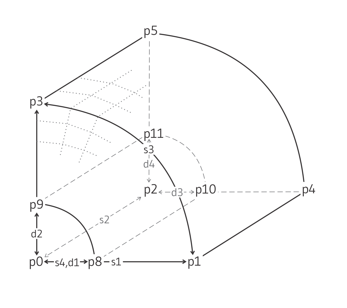
- cylindrical-shell [zonecreateblock]
Create a cylindrical shell mesh:

10 reference points, 4 size entries, 4 dimension entries,
fill-able.
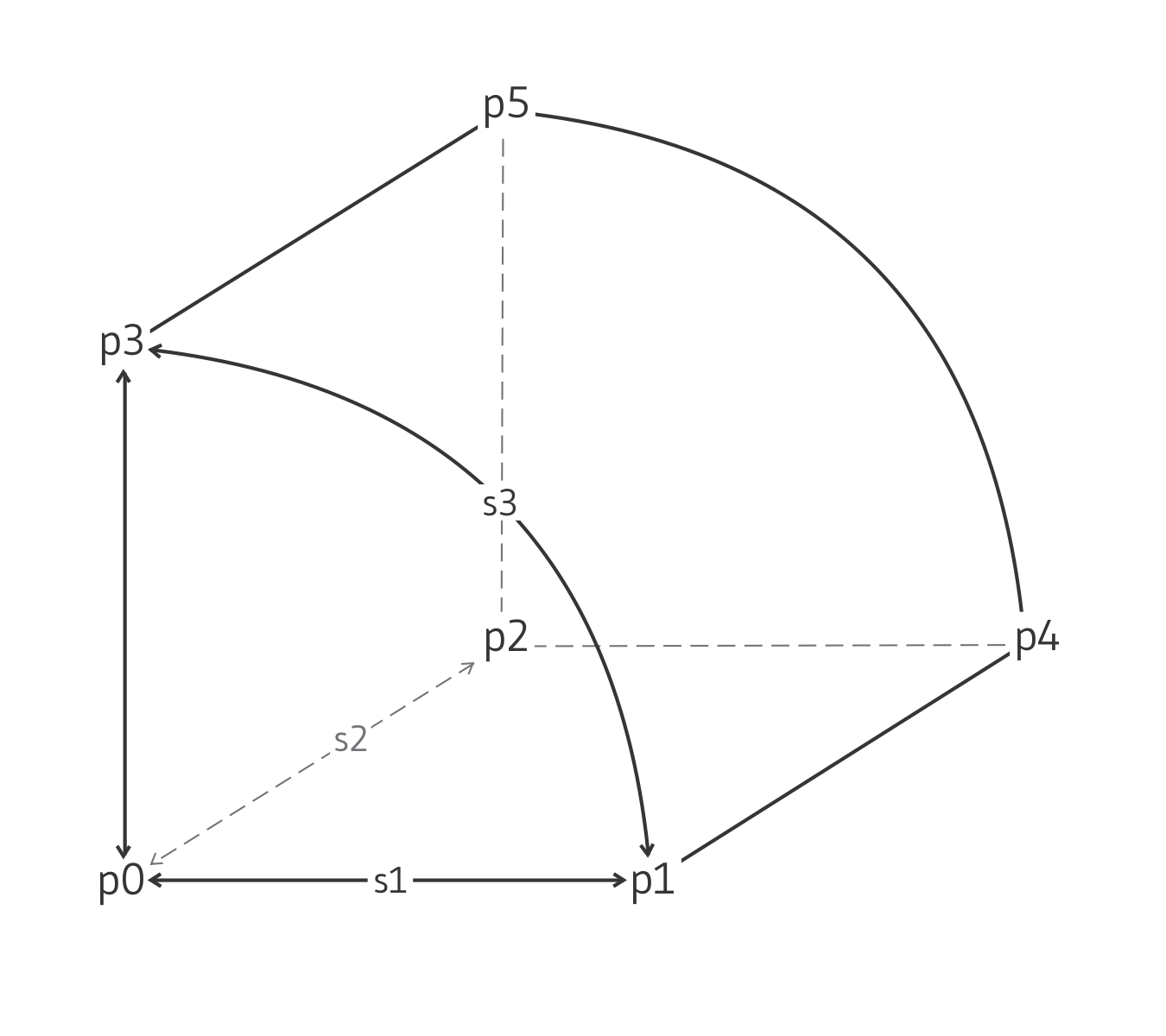
- cylinder [zonecreateblock]
Create a cylindrical-shaped mesh:

6 reference points, 3 size entries, 0 dimension entries, not
fill-able.
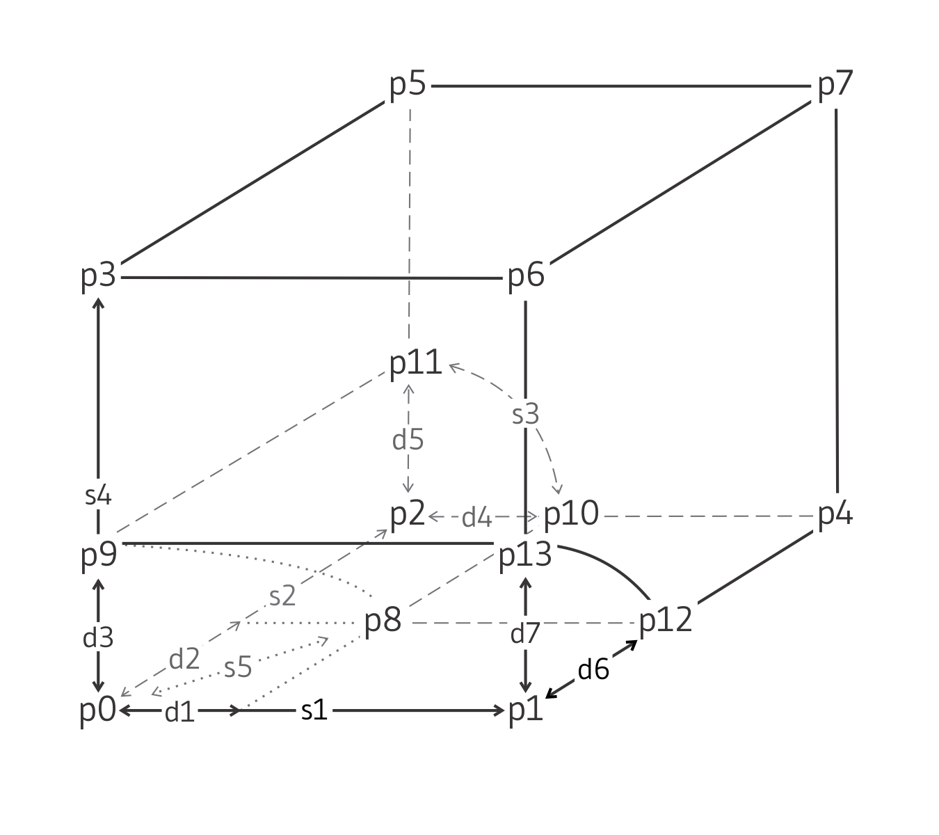
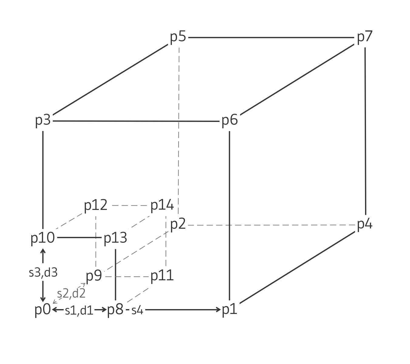
- cylindrical-intersection [zonecreateblock]
Create an intersection of two cylinders:

14 reference points, 5 size entries, 7 dimension entries,
fill-able.
- degenerate-brick [zonecreateblock]
Create a degenerate brick mesh, with two vertices merged:

7 reference points, 3 size entries, 0 dimension entries, not
fill-able.
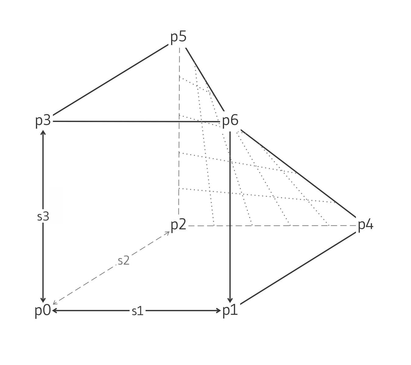
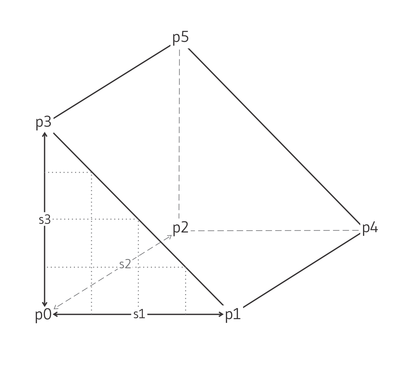
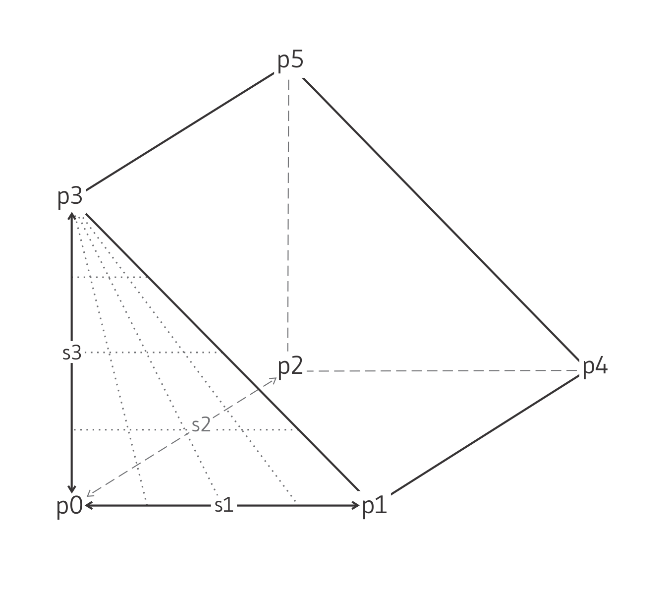
- pyramid [zonecreateblock]
Create a pyramid-shaped mesh:

5 reference points, 3 size entries, 0 dimension entries, not
fill-able.
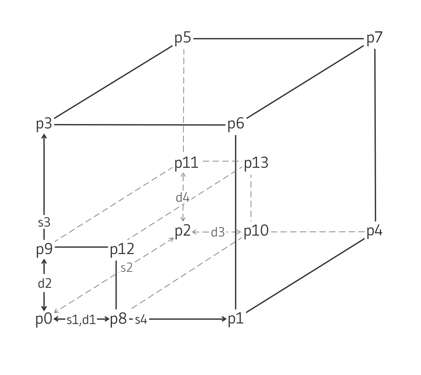
- radial-brick [zonecreateblock]
Create a radially graded mesh around brick:

15 reference points, 4 size entries, 3 dimension entries,
fill-able.
- radial-cylinder [zonecreateblock]
Create a radially graded mesh around cylindrical-shaped tunnel

12 reference points, 4 size entries, 4 dimension entries,
fill-able.
- radial-tunnel [zonecreateblock]
Create a radially graded mesh around parallelepiped-shaped tunnel:

14 reference points, 4 size entries, 4 dimension entries,
fill-able.
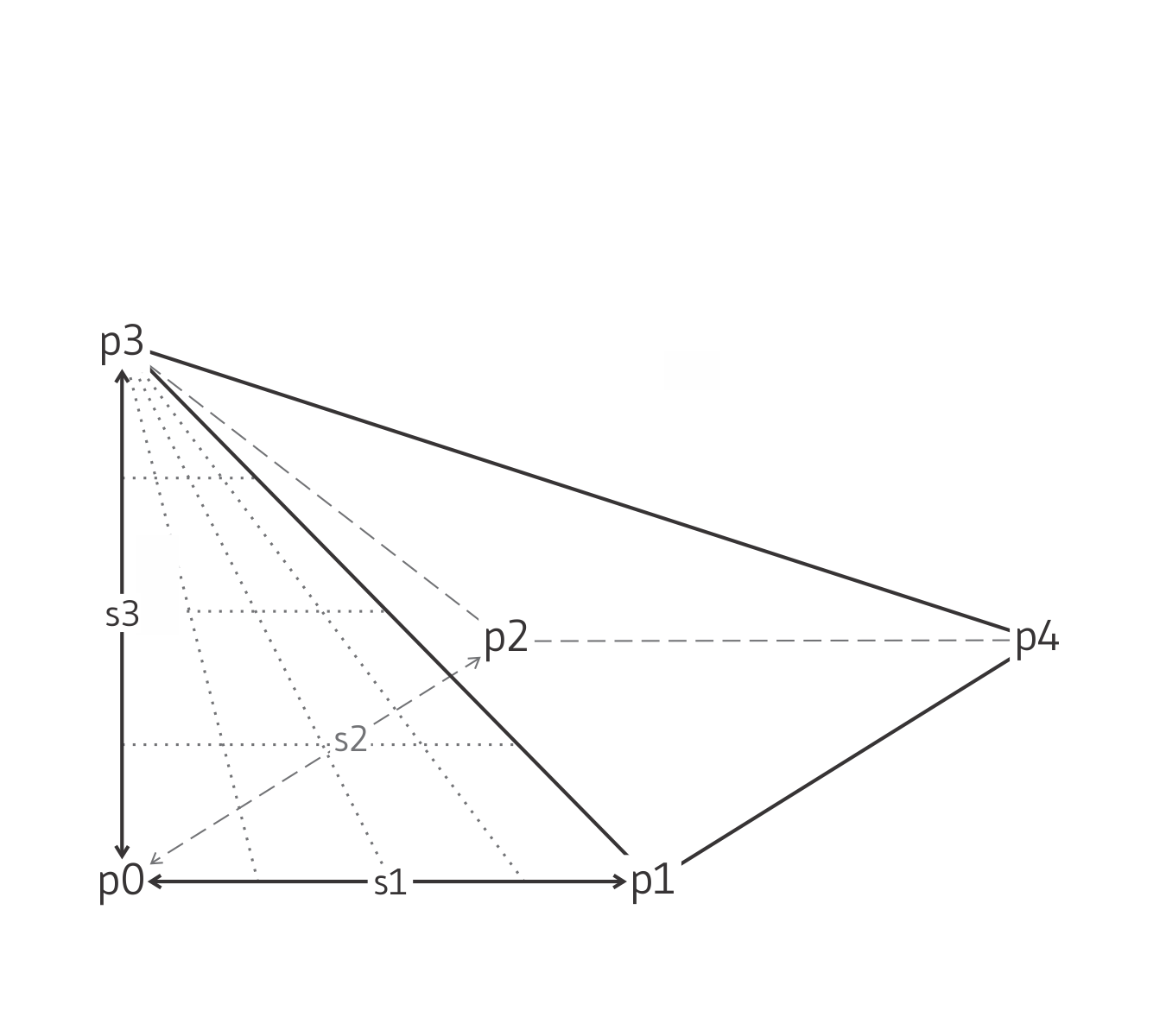
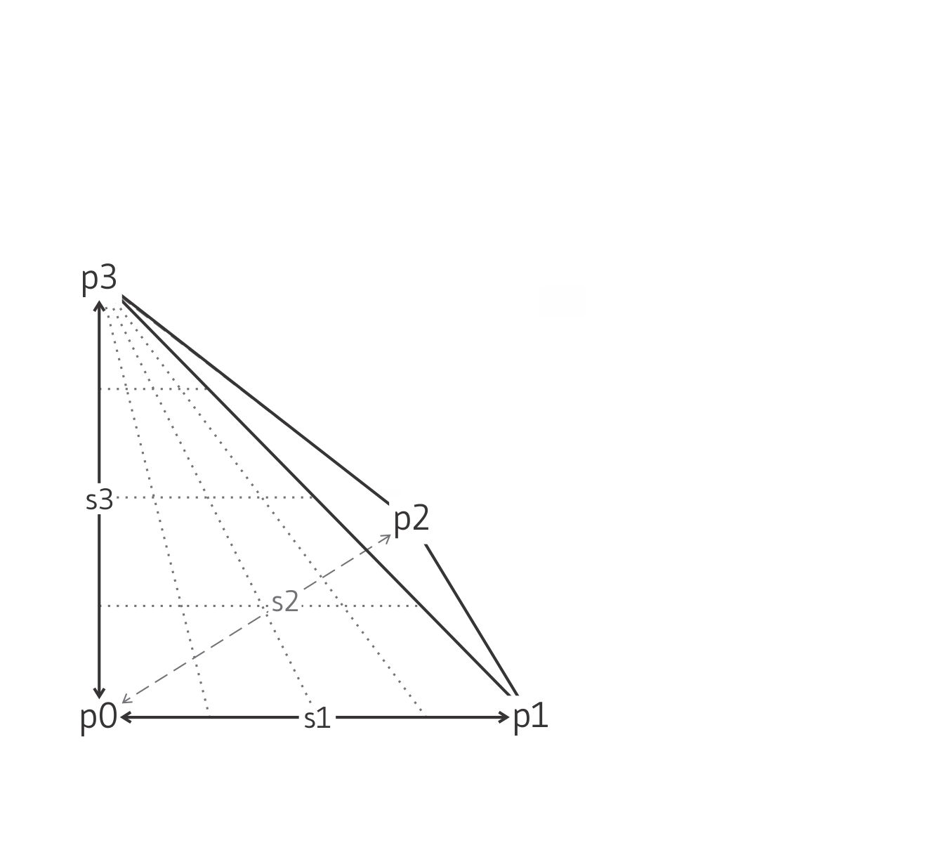
- tetrahedron [zonecreateblock]
Create a tetrahedral-shaped mesh:

4 reference points, 3 size entries, 0 dimension entries, not
fill-able.
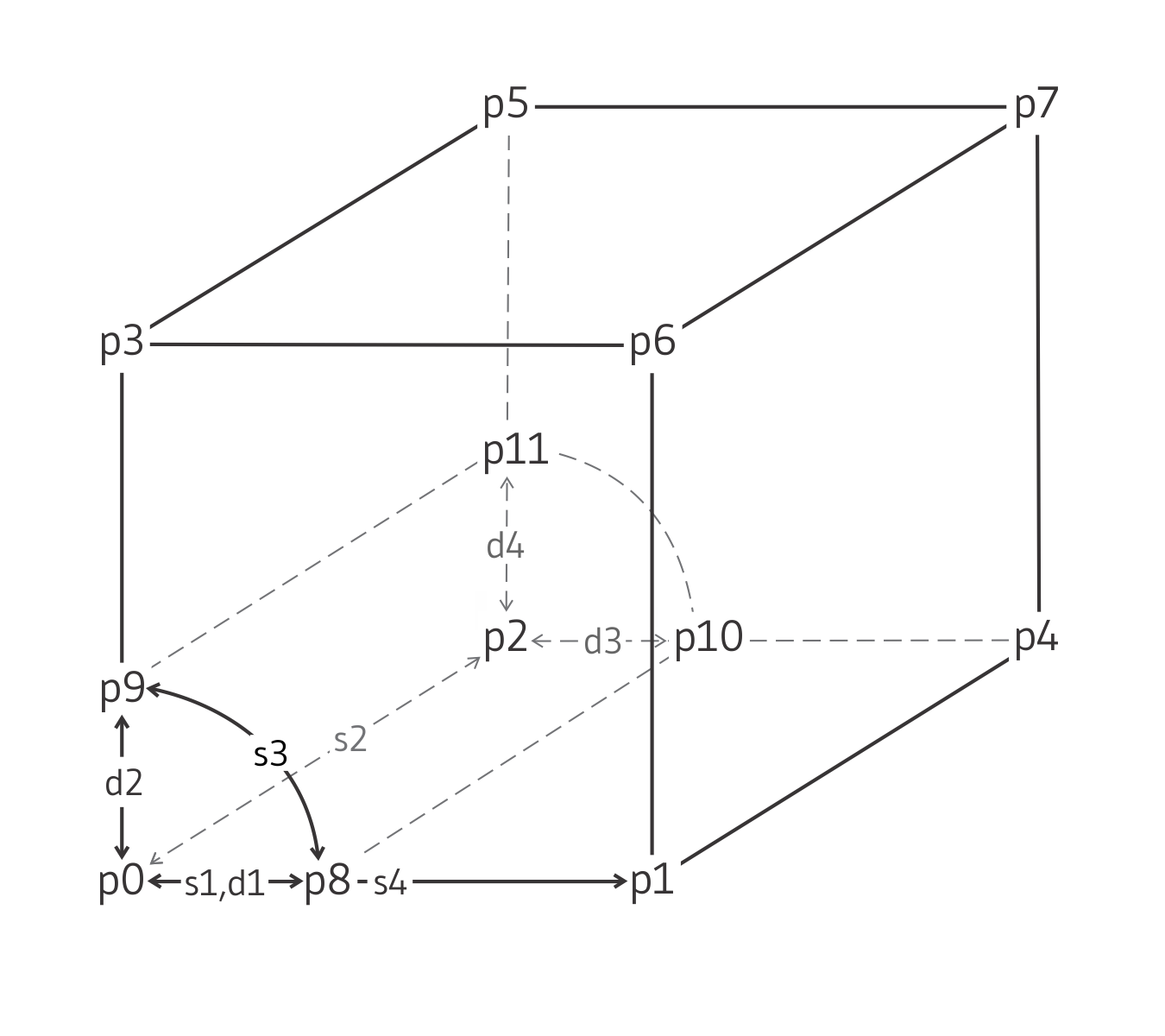
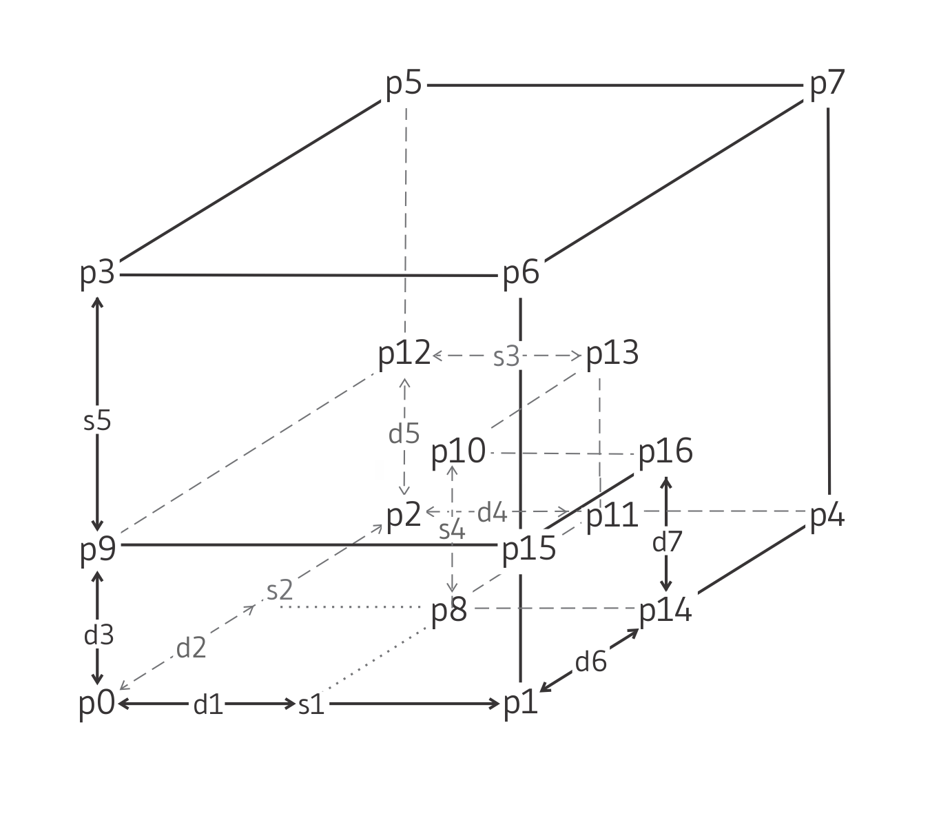
- tunnel-intersection [zonecreateblock]
Create a tunnel intersection:

17 reference points, 5 size entries, 7 dimension entries,
fill-able.
- uniform-wedge [zonecreateblock]
Create a uniform wedge-shaped mesh:

6 reference points, 3 size entries, 0 dimension entries, not
fill-able.
- wedge [zonecreateblock]
Create a wedge-shaped mesh:

6 reference points, 3 size entries, 0 dimension entries, not
fill-able.
Name/Keyword |
Reference Points |
Size Entries |
Dimension Entries |
Fill |
|---|---|---|---|---|
|
8 |
3 |
0 |
no |
|
7 |
3 |
0 |
no |
|
6 |
3 |
0 |
no |
|
6 |
3 |
0 |
no |
|
5 |
3 |
0 |
no |
|
4 |
3 |
0 |
no |
|
6 |
3 |
0 |
no |
|
15 |
4 |
3 |
yes |
|
14 |
4 |
4 |
yes |
|
12 |
4 |
4 |
yes |
|
10 |
4 |
4 |
yes |
|
17 |
5 |
7 |
yes |
zone create Keyword Block
The characteristics of the created shape (e.g., global coordinate positions, number of zones) are defined by specifying the keywords given below, after the shape keyword. The numerical entries associated with each shape are summarized in the table above and illustrated in the figures (click any thumbnail image above for a reference enlargement). The shape keywords of zone.create shown above will accept the keywords listed in the block below, except where noted otherwise in the descriptions. The major keywords are: brick, cylinder, cylindrical-intersection, cylindrical-shell, degenerate-brick, pyramid, radial-brick, radial-cylinder, radial-tunnel, tetrahedron, tunnel-intersection, uniform-wedge and wedge.
- dimension f ...
Specify the dimensions of interior regions for some shapes. These are used if the control point is not specifically given. Up to seven
dimensionentries may be required for a shape (f1, f2, f3, … , f7). Refer to the figures above for entries and dimensions. Ifdimensionis not given the entries are calculated as 20% of the lengths between reference points.This keyword can only be used with the following keywords of the zone create command: cylindrical-intersection, cylindrical-shell, radial-brick, radial-cylinder, radial-tunnel, and tunnel-intersection.
- edge f
Specify an edge length for the sides of the mesh. If
point1,point2, andpoint3are not specified, then the magnitude of the distance frompoint0will be defined byedge. By default the edge length is the number of zones specified in that direction.
- fill b <group s1 <slot s2 >>
If specified, the interior region for some shapes (see Summary of 3D Mesh Shape Properties above) will be filled with zones. If not specified, the interior region will not contain zones. If the optional
groupkeyword is given with a valid name, the name s1 is assigned to the filled zones.This keyword can only be used with the following keywords of the zone create command: cylindrical-intersection, radial-brick, radial-cylinder, radial-tunnel, and tunnel-intersection.
- group s1 <slot s2 >
Assign a group name s1 to this primitive at creation. By default (when the
slotkeyword is not supplied), the group is assigned to slotDefault. Use of the group logic is described in Groups.
- merge b
Gridpoints from newly created zones are merged with existing gridpoints if this keyword is set
true. During execution of azone.createcommand, a check is made for each gridpoint on new zones boundaries against the boundary gridpoints of zones that already exist. Internal gridpoints are not checked. If two boundary gridpoints fall within a tolerance of 1.e-7 (relative to the magnitude of the gridpoints’ position vector) of each other, they are assumed to be the same point, and existing gridpoint is used instead of creating new ones for all subsequent calculations. If merge is setfalse, two gridpoints are not merged into one.
- point i keyword
The keywords
point0,point1,point2…point16specify the reference (corner) points of shapes. By default,point0is located at (x = 0, y = 0, z = 0). By default,point1,point2, andpoint3are set to the orthogonal distances in the \(x\)-, \(y\)- and \(z\)-directions, with a magnitude equal to the number of zones in that direction. When specifyingpoint1,point2, andpoint3, the vectorspoint0-point1,point0-point2, andpoint0-point3must form a right-handed coordinate system.Up to 16 points may be required for a shape. The number required is shown in Summary of 3D Mesh Shape Properties above. The locations of these points are illustrated in the reference images (click on any thumbnail above to access).
The following options are available to define the location of any given point
- v <add>
The position is given as a vector v. If the optional keyword
addis used, the value of v will be added to the position ofpoint0.
- gridpoint s
The position of the gridpoint with name s is used. See the
zone gridpoint createcommand. This allows to user to create named reference points in space ahead of time, and refer to them when creating primitives.
- ratio f1 <f2... >
This specifies a ratio that is used to space zones with an increasing or decreasing geometric ratio. This ratio is defined as creating a zone size distribution such that each zone along the edge is f times the previous. Up to five ratio entries (
f5) may be needed for some shapes. For each shape, the entries and their associated zone directions are shown in the reference images (click any thumbnail above). Ifratiois not given, all entries default to 1.0.
- size i1 <i2 ... >
This specifies the number of zones for each shape. Up to five (
i5) may be needed for some shapes. The number required is listed in Summary of 3D Mesh Shape Properties above. The entries and their corresponding directions for each shape are shown in the reference images (click any thumbnail above). If not specified, size values default to 10.
- sweep-axis
When this keyword is given, edge
point0-point2is used as an axis about which edgespoint1-point4andpoint3-point5are swept. Without this keyword, the grid faces fall on the (point0,point1,point3) and (point2,point4,point5) planes.This keyword can only be used with the following keywords of the zone create command: cylinder, and cylindrical-shell.
above should be replaced with a js/jquery to make the style assignment
| Was this helpful? ... | Itasca Software © 2024, Itasca | Updated: Nov 12, 2025 |
