Examples • Verification Problems
Cylindrical Hole in an Infinite Hoek-Brown Medium (FLAC3D)
Problem Statement
Note
The project file for this example is available to be viewed/run in FLAC3D.[1] The project’s main data file is shown at the end of this example.
Stresses and displacements are calculated for the case of a cylindrical hole in an infinite Hoek-Brown medium subjected to an in-situ stress field and supported by an internal pressure. Consider a cylindrical hole with a radius \(b\) = 2 m, created within an infinite body under a uniform compressive stress of magnitude \(\sigma _{o}\) = 30 MPa. Support is provided by an internal pressure of \(p_i\) = 5 MPa.
The body has three material properties:
shear modulus (\(G\)) |
2.20 GPa |
bulk modulus (\(K\)) |
3.667 GPa |
density (\(\rho\)) |
2000 kg/m3 |
Values of the Hoek-Brown strength properties for the rock are
\(m_b\) |
1.7 |
\(s\) |
0.0039 |
\(a\) |
0.5 |
\(\sigma_{ci}\) |
30 MPa |
Closed-Form Solution
The analytical solution for this problem is provided by Carranza-Torres and Fairhurst (1999) for both associated plastic flow and nonassociated plastic flow (with zero dilation). In this verification exercise, only the case for nonassociated flow is presented.
The scaled far-field stresses, \(S_o\), and scaled internal pressure, \(P_i\), are determined by the following two equations:
The scaled critical internal pressure, \(P_{i}^{cr}\), at which the elastic limit of the stress state is reached, is calculated as
The critical internal pressure, \(p_{i}^{cr}\), is then
A plastic region develops uniformly around the hole because \(p_{i}<p_{i}^{cr}\). The extent of the failure zone is
The solution for the radial stress, \(\sigma_{r}\), and tangential stress, \(\sigma_{\theta}\), in the plastic region, \(r\leq b_{pl}\), is as follows:
The solution for the stress state in the elastic region, \(r > b_{pl}\), is
For the case of nonassociated flow with zero dilation, the radial displacement in the plastic region is
where: |
\(A_1\) |
= |
\(-K_{\psi}\); |
\(A_2\) |
= |
\(1 - \nu - \nu K_{\psi}\); |
|
\(A_3\) |
= |
\(\nu - (1-\nu) K_{\psi}\); |
|
\(C\) |
= |
\(A_2 - A_3\); |
|
\(D\) |
= |
\(A_2 \left[ 2 (1-A_1) \sqrt{P_{i}^{cr}} - 1 \right] - A_3 \left[ 2 (1-A_1) \sqrt{P_{i}^{cr}} - A_1 \right]\); |
|
\(K_{\psi}\) |
= |
\({{1 + \sin{\psi}}\over{1 - \sin{\psi}}}\); |
|
\(\psi\) |
= |
the dilation angle; |
|
\(G\) |
= |
shear modulus; |
|
\(\nu\) |
= |
Poisson’s ratio. |
FLAC3D Model
The FLAC3D model created for this problem is a plane-strain model with the plane of analysis oriented normal to the axis of the hole. Only a quarter of the problem needs to be analyzed, because of symmetry. The grid is shown in Figure 1. As the figure indicates, it is a radially symmetric mesh with increasing zone size away from the hole. The grid contains 3600 zones, and the boundary is located at 20 radii from the center of the hole. The constitutive model used for the simulation is the Hoek-Brown-PAC model.
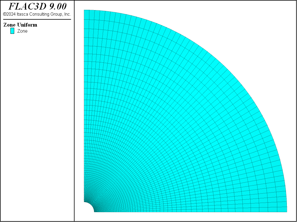
Figure 1: FLAC3D zone geometry for the plane-strain model.
Results and Discussion
The analytical solution for radial and tangential stresses and radial displacement provided in the equations shown above is programmed in the FISH functions in “check.dat”. The analytical results and FLAC3D results are then copied into tables for comparison. Table 4 shows the input that is required for the FISH functions to produce the analytical solutions and compare to FLAC3D results. The stresses and displacement are compared along a radial path measured from the center of the hole. The FISH variable radius_tunnel is the radius of the tunnel, rb_max defines the length of the normalized path (\(r\over{\_radius\_tunnel}\)), and \(\_npts\) defines the number of measurement points along the path.
Parameter name |
Value |
|---|---|
sig0 |
30e6 |
pi |
5e6 |
sigci |
30e6 |
mb |
1.7 |
s |
3.9e-3 |
G |
2.2e9 |
nu |
0.25 |
npts |
100 |
rb_max |
4.0 |
radius_tunnel |
2.0 |
Figure 2 shows the radial and tangential stresses calculated by FLAC3D compared to the analytical solution for \(\sigma_r\), and \(\sigma_\theta\). Figure 3 compares radial displacement, \(u_r\). The agreement is very good in both comparisons.
A plot of the Hoek-Brown failure envelope is shown in Figure 4. Zone stresses are shown on this plot and indicate the extent of the failed zone. Figure 5 displays the zone plasticity indicators, which also indicate the extent of the failure region. This corresponds to the analytical solution of 3.2 m (1).
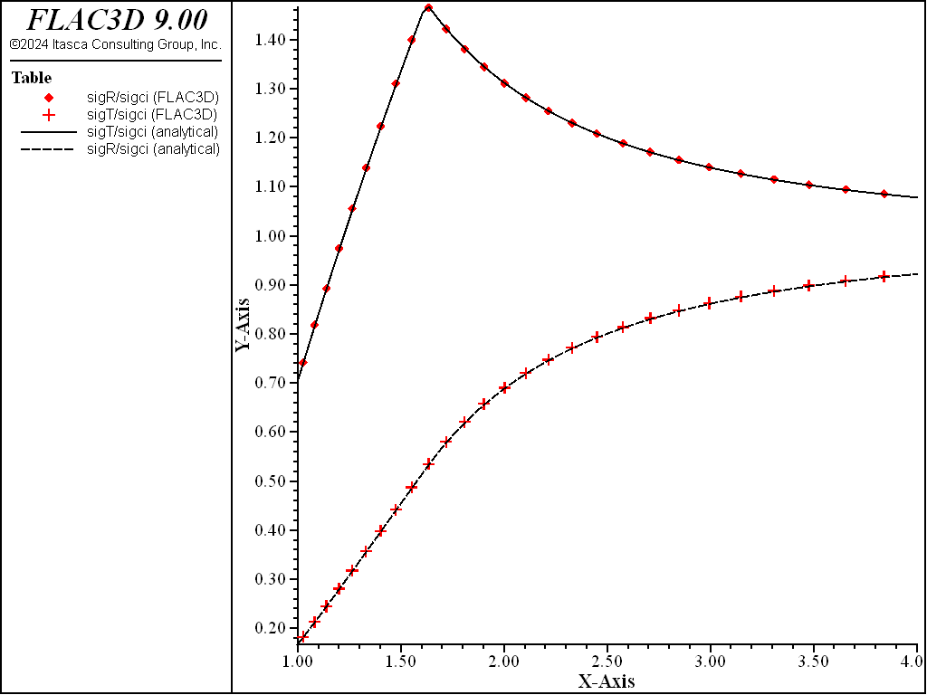
Figure 2: Comparison of \(\sigma_r\) and \(\sigma_\theta\) for the cylindrical hole in infinite Hoek-Brown medium (along normalized path 1 < r/_radius_tunnel < 4).
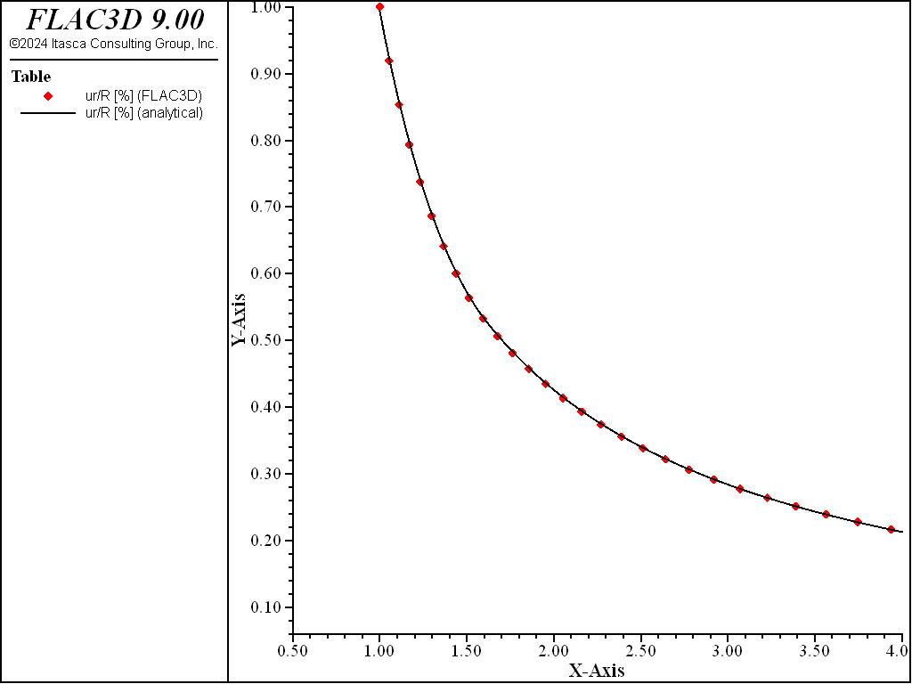
Figure 3: Comparison of \(u_r\) for the cylindrical hole in an infinite Hoek-Brown medium (along the normalized path 1 < r/_radius_tunnel < 4).
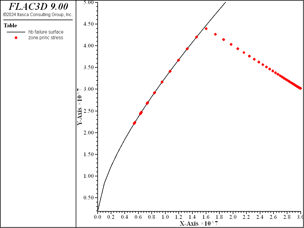
Figure 4: Hoek-Brown failure envelope.
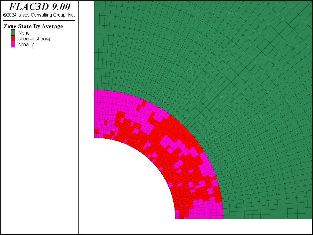
Figure 5: Plasticity indicators for Hoek-Brown model.
References
Carranza-Torres, C., and C. Fairhurst. “The Elasto-plastic Response of Underground Excavations in Rock Masses that Satisfy the Hoek-Brown Failure Criterion,” Int. J. Rock Mech. Min. Sci., 36, 777-809 (1999).
Hoek, E., and E. T. Brown. “Empirical Strength Criterion for Rock Masses,” J. Geotech. Engng. Div. ASCE, 106, 1013-1035 (1980).
Hoek, E., and E. T. Brown. Underground Excavations in Rock. London: IMM (1982).
Hoek E., and E. T. Brown. “The Hoek-Brown Failure Criterion — A 1988 Update,” in Rock Engineering for Underground Excavations (Proceedings of the 15th Canadian Rock Mechanics Symposium, October 1988), pp. 31-38. Toronto: University of Toronto, Department of Civil Engineering (1988).
Data File
CylinderInHoekBrownPAC.dat
model new
model large-strain off
model configure cluster
; Create zones
zone create cylindrical-shell point 0 (0,0,0) point 1 (40,0,0) ...
                              point 2 (0,0.2,0) point 3 (0,0,40) ...
                              dimension 2 ratio 1.05 size 60 1 60
; Assign constitutive model and properties
zone cmodel assign hoek-brown-pac
zone property bulk 3.66700006e9 shear 2.2e9 constant-s 0.0039 ...
              constant-mb 1.7 constant-sci 3.0e7 ...
              constant-a 0.5 stress-confining-prescribed 0.0 density 2000
; Initialize stress field
zone initialize stress xx -3e7 yy -3e7 zz -3e7
; Name the model boundaries
zone face skin
; Apply boundary conditions
zone face apply stress-normal -3e7 range group 'East'
zone face apply stress-normal -5e6 range group 'West1'
zone face apply velocity-normal 0.0 range group 'Bottom' or 'West2'
zone face apply velocity-normal 0.0 range group 'South' or 'North'
; Take some histories
model history mechanical ratio-local
; Solve the model
model solve ratio-local 1e-4
; Save the model
model save 'hoek'
Endnote
⇐ Smooth Circular Footing on an Associated Mohr-Coulomb Material (FLAC3D) | Cylindrical Hole in an Infinite Mohr-Coulomb Material (FLAC3D) ⇒
| Was this helpful? ... | Itasca Software © 2024, Itasca | Updated: Nov 12, 2025 |
