Lined Tunnel (with shell elements)
Problem Statement
Note
To view this project in FLAC3D, use the menu command . The main data file used is shown at the end of this example. The remaining data files can be found in the project.
This example demonstrates how to simulate the sequential operations of excavating and adding support to an advancing tunnel. The tunnel has a circular cross-section of 1 meter radius and is located at 5 meter depth in a soft elastic soil (\(K = 50\ \rm MPa\), \(G = 18\ \rm MPa\)) with isotropic in-situ stresses of 1 MPa. The tunnel is supported by shotcrete (\(E = 10.5\ \rm GPa\), \(\nu = 0.25\)) with a 200 mm thickness. The shotcrete remains elastic and rigidly connected to the soil throughout the simulation. (The shotcrete/soil interface can be allowed to fail in either tension or shear, such that gaps can form and slip can occur, if liner elements are used instead of shell elements — see Lined Tunnel (with liner elements).)
The geometry for this model was constructed interactively using the Extruder tool, and the data file exported from the State Record into “geometry.dat”. Figure 1 shows the resulting geometry and the group names assigned to zones and zone faces using the Extruder tool and the zone face skin command.
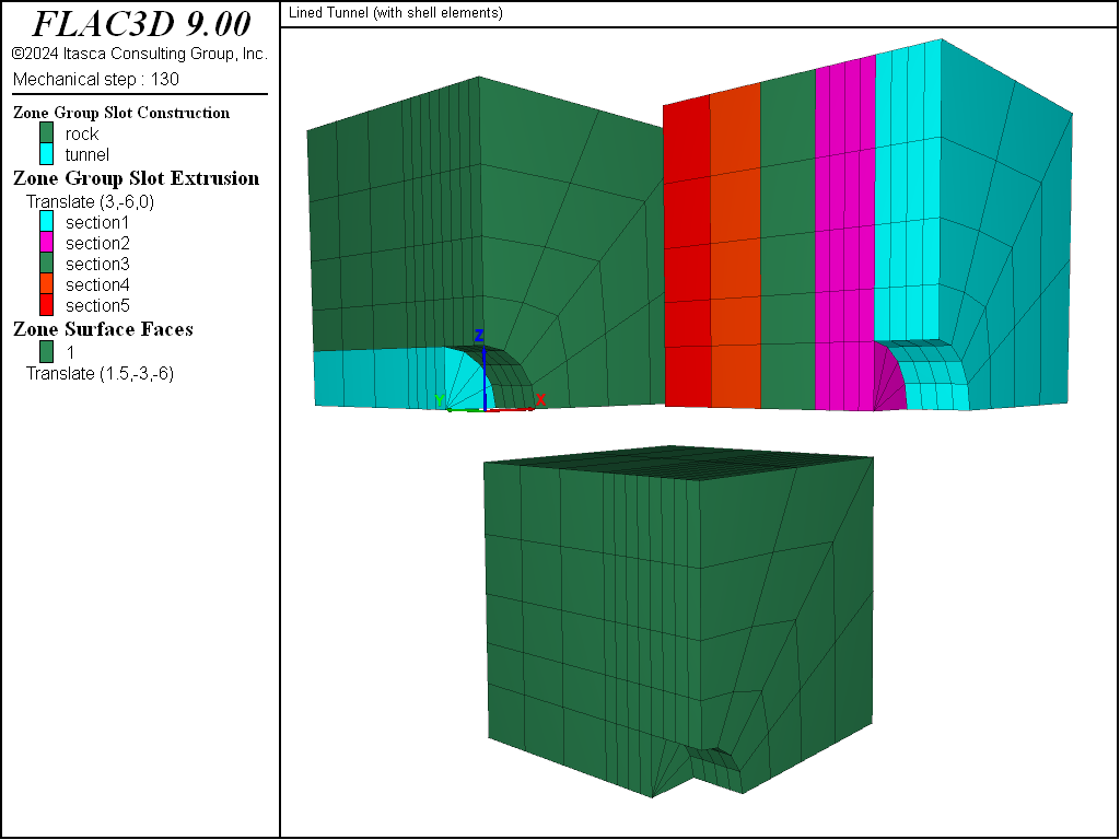
Figure 1: Model geometry with zone and face names assigned.
Begin with an initial tunnel of 2 meter total length. For simplicity, it is assumed that the excavation proceeds simultaneously on both tunnel faces; therefore, it is only necessary to model one quarter-section of the tunnel by applying symmetry boundary conditions (zero displacement normal to the plane, and zero rotation about two axes that lie in the plane) on the three symmetry planes. The excavation process is modeled by assigning the null material model to zones, and then allowing the stresses to redistribute. The shotcrete is now installed by creating shell elements and attaching them to the tunnel surface with the structure shell create by-zone-face command. The next tunnel segment is excavated and, again, the stresses are allowed to redistribute. The model at this stage is shown in Figure 2. This excavation sequence can be repeated to model the entire tunnel-construction process.
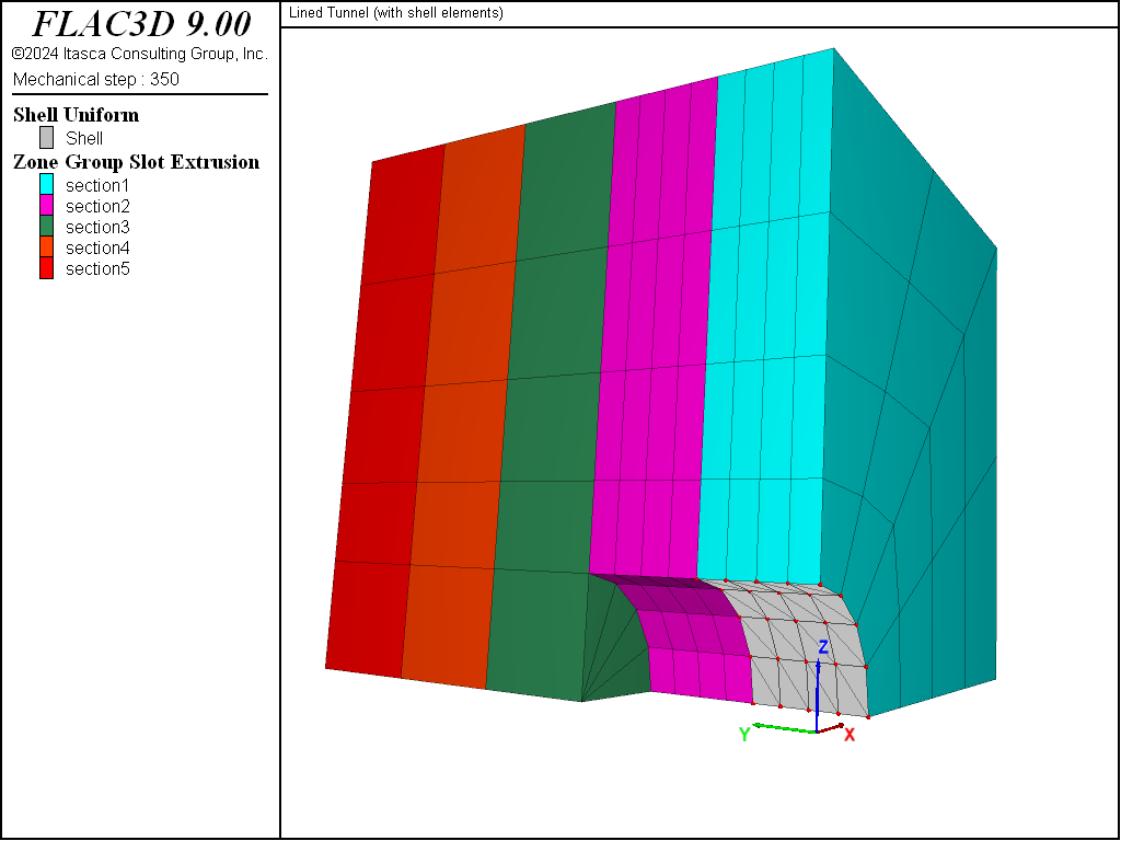
Figure 2: Stage 2: Install shotcrete in section 1; excavate material in section 2.
Figures 3 and 4 show the displacement of the soil during the second excavation stage for the cases with and without support. The \(z\)-displacement history at the tunnel crown (\(z\) is vertical) is included in each figure. The shotcrete support reduces the crown displacement from approximately 12 mm to 1 mm.
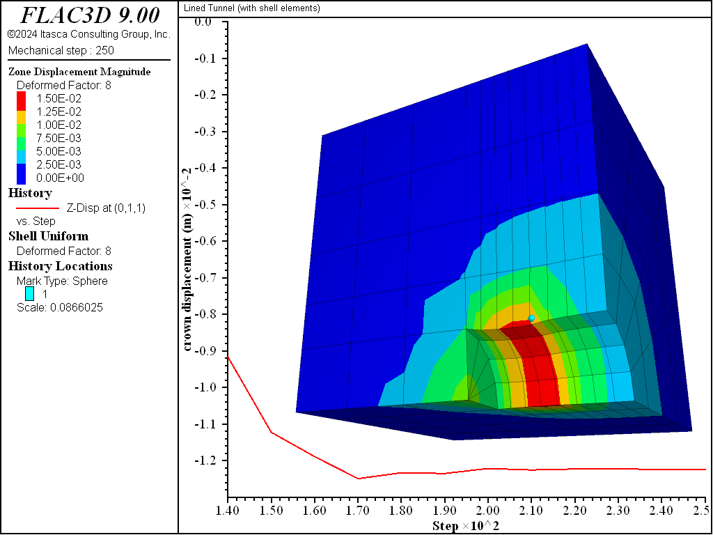
Figure 3: Displacement of the soil (deformation factor: 8) during stage 2 — no support.
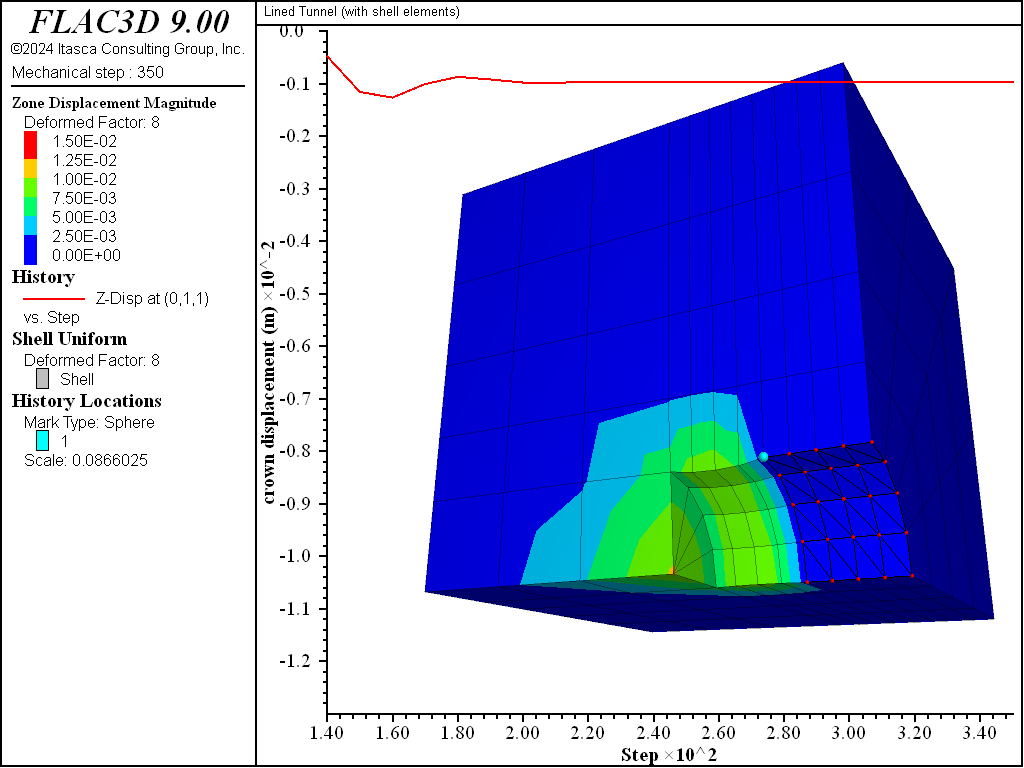
Figure 4: Displacement of the soil (deformation factor: 8) during stage 2 — shotcrete support.
The deformation arising from the excavation of material in section 2 forces the front of the liner near the tunnel face to pinch inwards (see Figure 5). This pinching induces a thrust in the circumferential direction (see Figure 6). The thrust is measured by the membrane stress resultant \(N_y\), where the \(y\)-direction lies along the tunnel circumference (see Figure 7). We see that the thrust is compressive, and that it is largest at the front of the liner and decreases with increasing distance from the front. This response mirrors that of the pinching deformation, with greater pinching inducing greater thrust.
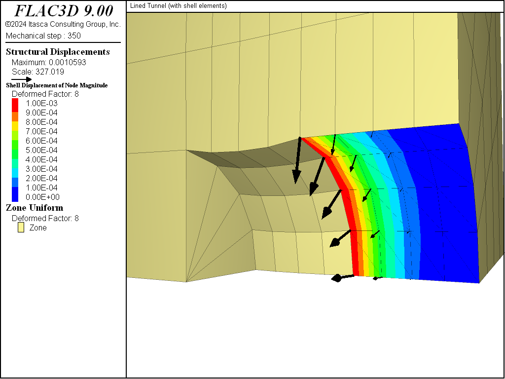
Figure 5: Pinching deformation in the liner at end of stage 2.
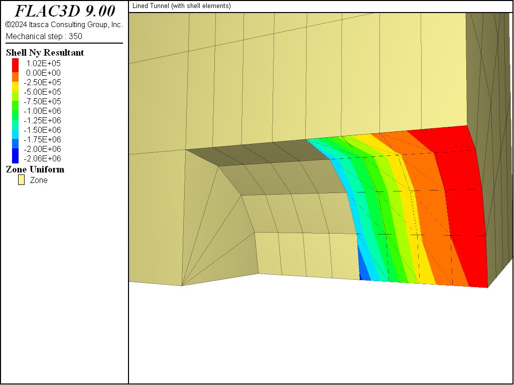
Figure 6: Thrust in the liner at end of stage 2.
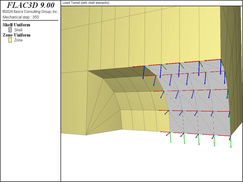
Figure 7: Surface coordinate system in the liner ({red,green,blue} = {x, y, z}).
One additional excavation stage is performed. The model at the end of this stage is shown in Figure 8. The shotcrete support has been extended into tunnel section 2 by issuing another structure shell create by-zone-face command and specifying an ID number for the new shell segment that differs from the ID number of the shell segment in tunnel section 1. This creates a “cold-joint” between the two shell segments.[1] The deformation that occurs during stage 3 begins to load the new shell segment, and produces additional load in the previous shell segment. Both the displacement (see Figure 9) and the thrust (see Figure 10) fields are discontinuous across the joint.
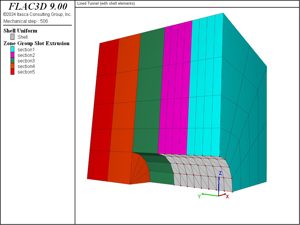
Figure 8: Stage 3: Install shotcrete in section 2; excavate material in section 3.
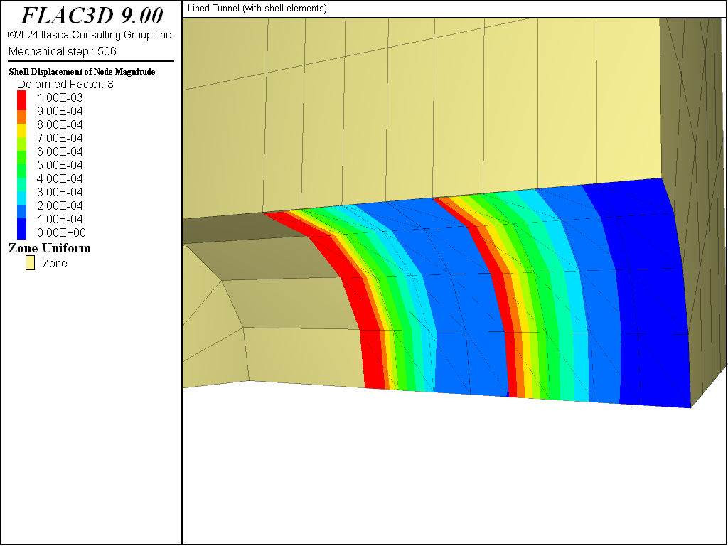
Figure 9: Liner displacement at end of stage 3.
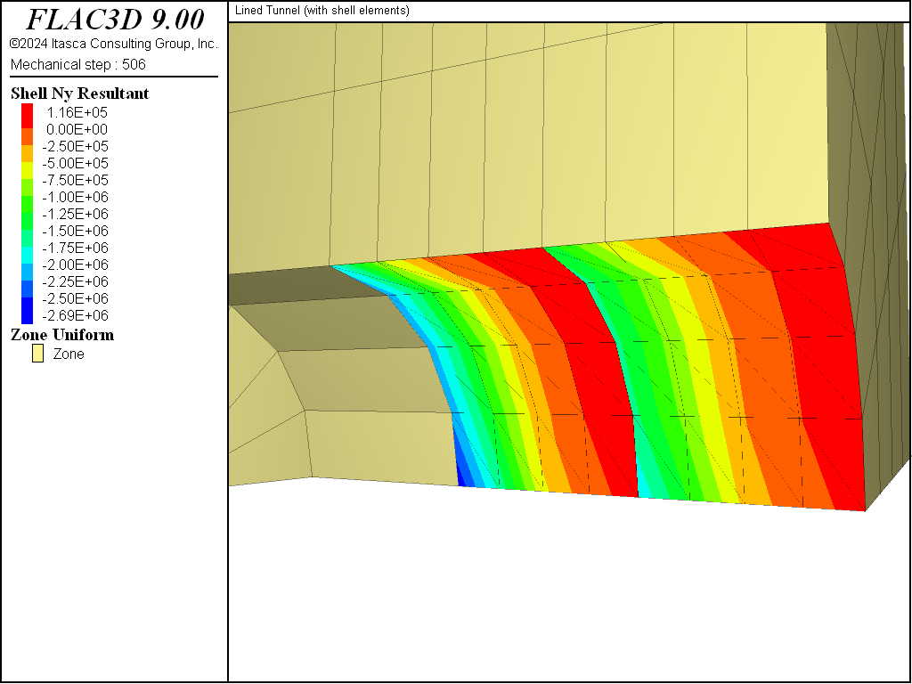
Figure 10: Thrust in the liner at end of stage 3.
Endnotes
Data File
LinedTunnelShell.dat
model new
model large-strain off
model title 'Lined Tunnel (with shell elements)'
; Create simple zone geometry, created interactively in Sketch
; and exported from the State Record
program call 'geometry' suppress
; Also assigns group names to model zones and faces.
zone generate from-sketch
zone face skin ; Label model boundaries
; Material model for soil and soil properties
zone cmodel assign elastic
zone property bulk 50e6 shear 18e6
; Initial conditions
zone initialize stress xx -1e6 yy -1e6 zz -1e6
; Boundary Conditions - rollers on near boundaries and fully fixed on far.
zone face apply velocity-normal 0 range group 'West'
zone face apply velocity-normal 0 range group 'South'
zone face apply velocity-normal 0 range group 'Bottom'
zone face apply velocity (0,0,0) range group 'East' or 'North' or 'Top'
; --- Stage 1: excavate tunnel section 1
zone cmodel assign null range group 'section1' group 'tunnel'
model solve convergence 1
model save 'Stage1'
; Reset displacements, take history of roof closure
zone gridpoint initialize displacement (0,0,0)
zone history displacement-z position (0,1,1)
; --- Stage 2: excavate tunnel section 2
zone cmodel assign null range group 'section2' group 'tunnel'
model save 'Stage2-start'
model solve convergence 1
model save 'Stage2-nosupport'

; -- Rerun, but this time, with support.
model restore 'Stage2-start'
; --- Add shotcrete on 'shotcrete' zone faces in section 1.
structure shell create by-zone-face group 'shotcrete1' ...
                    range group 'shotcrete' group 'section1'
structure shell cmodel assign elastic
structure shell property young 10.5e9 poisson 0.25 thickness=0.2
; --- Boundary (symmetry) conditions for structural elements
structure node fix velocity-x rotation-y rotation-z range position-x 0
structure node fix velocity-y rotation-x rotation-z range position-y 0
structure node fix velocity-z rotation-x rotation-y range position-z 0
model solve convergence 1
structure shell recover surface (0,1,0) ; surface-y is circumferential
structure shell recover resultants
model save 'Stage2-support'
; --- Stage 3: excavate tunnel section 3
zone cmodel assign null range group 'section3' group 'tunnel'
; --- Add shotcrete on 'shotcrete' zone faces in section 2.
structure shell create by-zone-face group 'shotcrete2' ...
                    range group 'shotcrete' group 'section2'
structure shell cmodel assign elastic
structure shell property young 10.5e9 poisson 0.25 thickness=0.2
; --- Boundary (symmetry) conditions for structural elements
structure node fix velocity-x rotation-y rotation-z range position-x 0
structure node fix velocity-y rotation-x rotation-z range position-y 0
structure node fix velocity-z rotation-x rotation-y range position-z 0
model solve convergence 1
structure shell recover surface (0,1,0) ; surface-y is circumferential
structure shell recover resultants
model save 'Stage3-support'
| Was this helpful? ... | Itasca Software © 2024, Itasca | Updated: Nov 12, 2025 |
