Plastic Hinge Formation (with shell elements)
Problem Statement
Note
To view this project in FLAC3D, use the menu command . The data file used is shown at the end of this example.
This example demonstrates a procedure by which FLAC3D can be used to calculate the initiation and subsequent behavior of a plastic hinge line that forms within a shell structure. The double-node method described in Plastic Hinge Formation (with beam elements) is replicated using shell elements. Double nodes are created along the hinge line, and then linked together. The double nodes allow a discontinuity in the rotation to occur when the limiting plastic moment is reached. For shell elements, there is no analog to the single-node method that can be used to model plastic hinges in beam elements.
Analytical Solution
The analytical solution and particular problem to be considered are given in Plastic Hinge Formation (with beam elements).
FLAC3D Models, Results and Discussion
The FLAC3D model simulates a beam of 10-m length, 1-m width and 0.1-m thickness (see Figure 1). A cross-diagonal mesh pattern is used to ensure symmetric response, and a DKT-CST Hybrid Shell Element is used to support the membrane loading that will develop after failure if the problem is run in large-strain mode. The isotropic elastic constitutive model is used with a Young’s modulus and Poisson’s ratio of 200 GPa and 0.3, respectively.
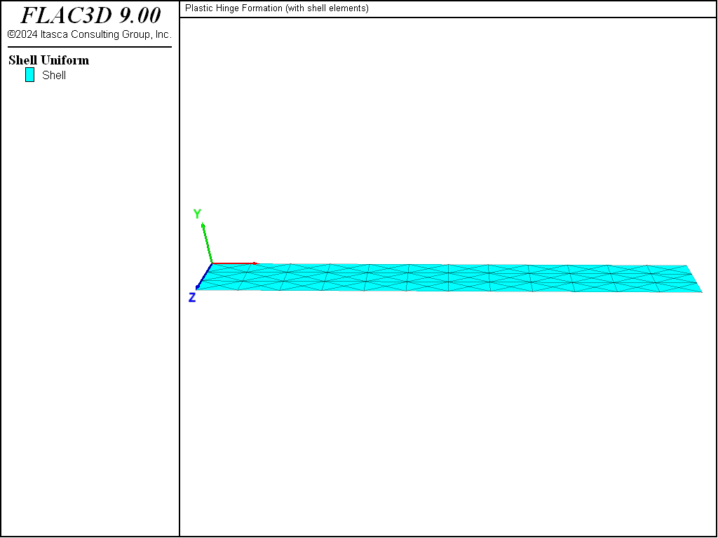
Figure 1: Geometry of the FLAC3D model showing mesh and global coordinate system.
Two separate structure shell create commands are issued to produce a model containing two separate shell sections: one for the left half of the beam, and the other for the right half of the beam. Figure 2 shows the shell elements near the beam center with the nodes drawn, and the elements shrunk by a factor of 0.8 (via the Shrink attribute of the plot item).

Figure 2: Shell elements at beam center with nodes drawn as spheres.
Notice that there is a set of eight nodes that overlap along the beam center line. These overlapping nodes are linked together with the following commands[1]:
struct node join range group 'leftSide' ; source node is on left side
                                        ; target node is on right side
struct link attach rotation-z normal-yield
struct link property rotation-z area 1.0 stiffness 2e9
struct link property rotation-z yield-compression 8.33e3 yield-tension 8.33e3 ...
                     range position-x 5.0 position-z 0.3 0.7
struct link property rotation-z yield-compression 4.17e3 yield-tension 4.17e3 ...
                     range position-x 5.0 position-z 0.0
struct link property rotation-z yield-compression 4.17e3 yield-tension 4.17e3 ...
                     range position-x 5.0 position-z 1.0
The first command creates node-to-node links joining each node on the left side with the overlapping node on the right side. The links are shown in Figure 3, and the attachment conditions are rigid for all degrees-of-freedom. The second command inserts normal-yield springs in the \(z\)-rotational direction of all links. The final four commands set the properties of these normal-yield springs as follows. We set all areas to unity, and we set both the compressive and tensile yield strengths equal to the desired plastic-moment capacity (based on the tributary length associated with each node). The total plastic-moment capacity is 25 kN-m, so we assign 8.33 kN-m to the two center springs and 4.17 kN-m to the two end springs. Finally, we set the spring stiffness equal to a value that is large enough to make the spring deformation small relative to the shell deformation. We choose a value of \(2 \times 10^9 \textrm{ N} \, \textrm{m}\), which is approximately 10 times larger than the \(z\) rotational stiffnesses of the nodes in the model.[2]
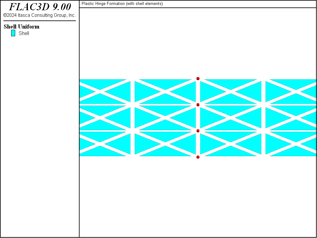
Figure 3: Shell elements at beam center with links drawn as spheres.
Now that the overlapping nodes have been appropriately linked to one another, simple supports are specified at the beam ends by restricting translation in the \(y\)-direction. A constant vertical velocity is applied to the four target nodes on the right section. The \(M_x\) stress resultant (with the \(x\) direction of the surface system aligned with the \(x\) direction of the global system) at the centroid of an element near the center is monitored during the calculation to determine when the limiting moment is reached. The total moment acting at the beam center is found by multiplying \(M_x\) by the 1-m width of the beam; thus, the total moment is given by \(M_x\).
A 20-mm displacement is applied to the four target nodes (at the beam center and on the right side), and the limiting moment is reached (see Figure 4). The moment at the beam center is found to be 25.8 kN, which is within 3.2% of the specified moment capacity (see Figure 5). A hinge has developed at the beam center (see Figure 6).
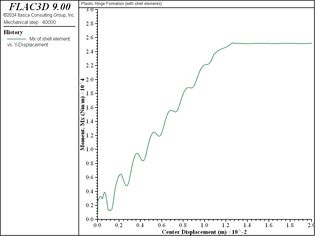
Figure 4: Moment at centroid of an element near the center versus applied center displacement.
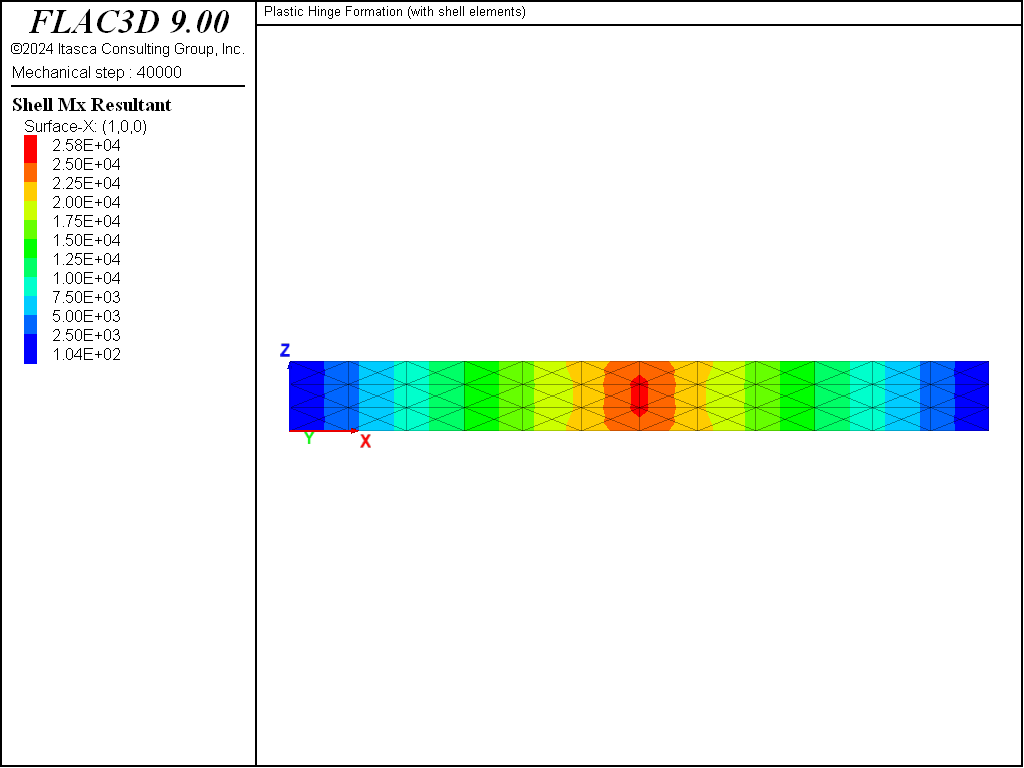
Figure 5: Variation of the \(M_x\) stress resultant over the beam.
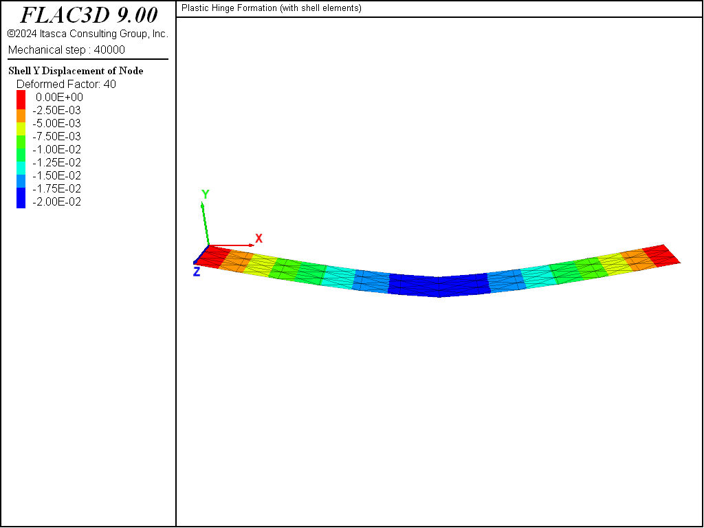
Figure 6: Transverse displacement plotted on deformed shape of beam (deformation factor: 40).
Endnotes
Data File
PlasticHingeShell.dat
model new
model large-strain off
model title 'Plastic Hinge Formation (with shell elements)'
; Create shell elements in two groups
structure shell create by-quadrilateral (0,0,0) ( 5,0,0) ( 5,0,1) (0,0,1) ...
                                     size (6,3) id=1 element-type=dkt-csth ...
                                     cross-diagonal group 'leftSide'
structure shell create by-quadrilateral (5,0,0) (10,0,0) (10,0,1) (5,0,1) ...
                                     size (6,3) id=2 element-type=dkt-csth ...
                                     cross-diagonal group 'rightSide'
structure shell cmodel assign elastic
structure shell property young 200e9 poisson 0.3 thickness 0.1
; Create links at overlapping nodes and set their properties.
structure node join range group 'leftSide' ; source node is on left side
                                        ; target node is on right side
structure link attach rotation-z normal-yield
structure link property rotation-z area 1.0 stiffness 2e9
structure link property rotation-z yield-compression 8.33e3 yield-tension 8.33e3 ...
                     range position-x 5.0 position-z 0.3 0.7
structure link property rotation-z yield-compression 4.17e3 yield-tension 4.17e3 ...
                     range position-x 5.0 position-z 0.0
structure link property rotation-z yield-compression 4.17e3 yield-tension 4.17e3 ...
                     range position-x 5.0 position-z 1.0
; Boundary conditions (move the target nodes)
structure node fix velocity-y range position-x  0.0
structure node fix velocity-y range position-x 10.0
structure node fix velocity-y range position-x 5.0 group 'rightSide'
structure node initialize velocity-y -5e-7 local ...
                       range position-x 5.0 group 'rightSide'

structure node history displacement-y position (5.0,0,0.6667)
structure shell history resultant-mx surface-x 1,0,0 position (4.861,0,0.5)

structure mechanical damping combined-local
model cycle 40000 ; 20 mm total displacement
model save 'PlasticHingeShell'
⇐ Elastic-Plastic Plate (Collapse Load) with Uniform Lateral Load | Lined Tunnel (with shell elements) ⇒
| Was this helpful? ... | Itasca Software © 2024, Itasca | Updated: Nov 12, 2025 |
