Steady-State Fluid Flow with a Free Surface (FLAC2D)
Note
The project file for this example is available to be viewed/run in FLAC2D.[1] The main data files used are shown at the end of this example. The remaining data files can be found in the project.
This numerical simulation analyzes the steady-state seepage flow through a homogeneous embankment with vertical slopes exposed to different water levels and resting on an impermeable base. The total discharge, Q, and the length of seepage face, s, are compared to the exact solutions. The problem tests FLAC2D’s formulation for unconfined groundwater flow. Figure 1 shows the geometry and boundary conditions of the problem.
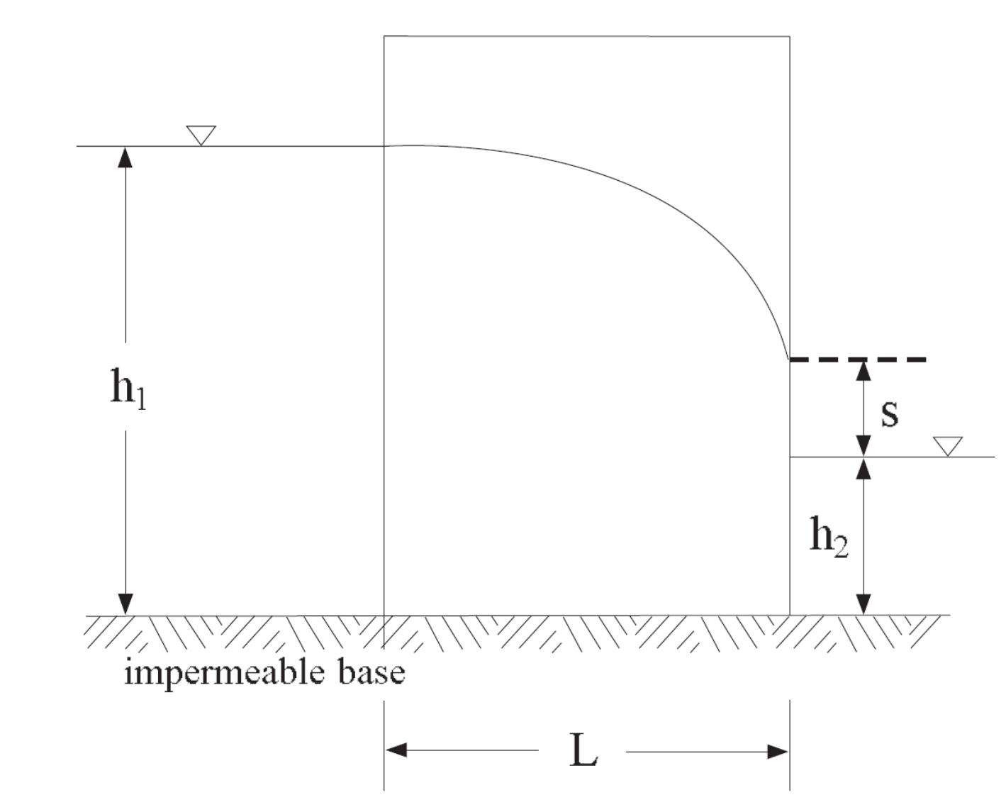
Figure 1: Problem geometry and boundary conditions.
The dimension and elevations are:
\(L\) |
= 9 m |
\(h_1\) |
= 6 m |
\(h_2\) |
= 1.2 m |
The following material properties are used.
permeability (k) |
10−10 (m/sec)/(Pa/m) |
porosity (n) |
0.3 |
water density (ρw) |
1000 kg/m3 |
water bulk modulus (Kw) |
1000 Pa |
soil dry density (ρ) |
2000 kg/m3 |
gravity (g) |
10 m/sec:sup:\(2\) |
Dupuit’s formula (see, for example, Davis and DeWiest 1966, p. 186) gives the exact solution for the total flow rate (per unit model thickness) as
For this particular case, the value for \(Q\) is 1.92 × 10⁻⁶ m3/s. The length, s, of the seepage face as a function of the characteristic dimensions of the section was obtained by Polubarinova-Kochina and is given in Figure 2 (see, e.g., Harr 1991, pp. 206-207). For this particular problem, \(h_2/h_1 = 0.2\), \(L/h_1 = 1.5\), and the value of \(s/h_1\) is evaluated from the graphs at 0.1, which gives an elevation \(s\) = 0.6 m.
Two cases have been studied, corresponding to two different initial conditions:
CASE 1: The embankment is initially dry (saturation = 0), and the sides are suddenly exposed to the water.
CASE 2: The water level at both sides is initially the same (\(h_1\) = \(h_2\) = 6 m), followed by a sudden drawdown at the right side (\(h_2\) = 1.2 m).
The grid and boundary conditions are the same for both cases. Both cases use the cutoff unsaturated flow model with a cutoff and tension value of zero. The only difference is the initial pore-pressure distribution. In Case 1, saturation and pore pressure are zero inside the mesh; in Case 2, saturation is 1 for all gridpoints, and the pore pressure inside the mesh follows a gravitational gradient.
The material properties are assigned as described above. Because only the steady-state fluid flow solution is of interest in this problem, the mechanical behavior of the soil and its interaction with the groundwater flow are not addressed. The absolute values of soil density, homogeneous permeability and porosity are not relevant to the final solution, and the water bulk modulus is given a small value, compatible with free surface numerical stability, to speed up the calculation to steady state.
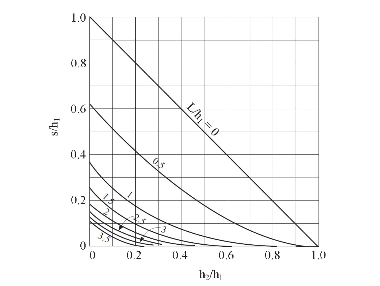
Figure 2: Seepage face solution after Polubarinova-Kochina
The model is solved for 4.5e8 seconds (or approximately 14 years) to ensure arrival at the steady state. Alternatively, the ratio-flow convergence criteria could have been used with the model solve-fluid command, which returns the ratio of the difference between inflow and outflow to the total inflow and outflow in the model. At the solution approaches steady-state this value approaches zero.

Figure 3: Steady-state flow vectors and seepage face solution (Case 1).
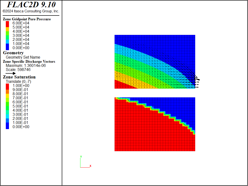
Figure 4: Steady-state flow vectors and seepage face solution (Case 2).
Both cases are run in both explicit and implicit modes - to verify that the implicit solver works correctly when using the cutoff saturation model. In the implicit case the servo is used to automatically switch from explicit to implicit after the initial strong transient.
In the project file you can see that a sanity check is also done using both an attached boundary and a boundary connected using interfaces.
In addition the final state is calculated directly using the zone fluid steady-state command, to show that this command also works for unsaturated flow using the cutoff model. The steady state solution is also obtained for a fully saturated system.
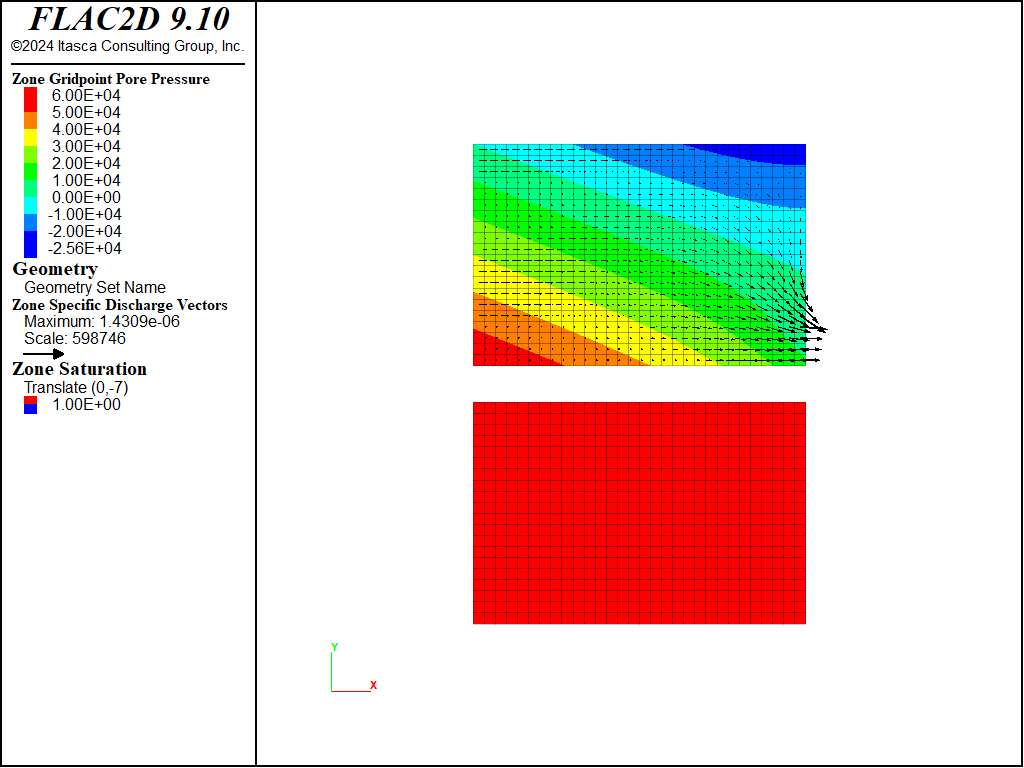
Figure 5: Steady-state flow vectors and seepage face calculated for a fully-saturated mode.
Finally both the transient and steady-state solutions are made using the Gardner unsaturated flow model, with constants selected somewhat artifically to create a phreatic surface about the width of the mesh. This allows reasonable comparison with the cutoff model.
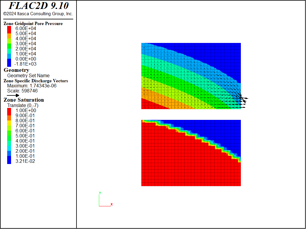
Figure 6: Steady-state flow vectors and seepage face calculated for the Gardner unsaturated flow model.
Reference
Davis, S. N., and R. J. DeWiest. Hydrogeology. J. Wiley (1966).
Harr, M. E. Groundwater and Seepage. Dover (1991).
Data Files
FreeSurfaceSteadyStateFluidFlow-Case1.dat
model new
model title "Steady state flow through a vertical embankment - case 1"
zone create quadrilateral size 30 20 point 1 (9.0,0) point 2 (0,6.0) ...
                            point 3 (9.0,6.0)
zone face skin
zone face group 'BC=Outflow' range group 'East' position-y 0 1.19
; --- fluid flow model ---
model configure fluid-flow
zone fluid unsaturated cutoff 0
zone fluid property mobility-coefficient 1e-10 porosity 0.3
zone fluid property fluid-modulus 1e3 fluid-density 1e3
zone gridpoint initialize saturation 0
zone face apply pore-pressure 6.0e4 gradient 0 -1e4 range group 'West'
zone face apply pore-pressure 1.2e4 gradient 0 -1e4 range group 'Outflow'
zone face apply pore-pressure-maximum range group 'East' or 'Top' group 'Outflow' not
; Add particle tracks
zone fluid track create line begin (0,0.5) end (0,5.5) ...
                             segments 12 group "set1"
zone fluid track active on
; --- settings ---
model gravity 10
model save 'case1s'
model solve-fluid time 4.5e8 ; 6e7
model save 'case1e'

model restore 'case1s'
zone fluid implicit servo on
model solve-fluid time 4.5e8 ; 6e7
model save 'case1i'
FreeSurfaceSteadyStateFluidFlow-Case2.dat
model new
model title "Steady state flow through a vertical embankment - case 1"
zone create quadrilateral size 30 20 point 1 (9.0,0) point 2 (0,6.0) ...
                               point 3 (9.0,6.0)
zone face skin
zone face group 'BC=Outflow' range group 'East' position-y 0 1.19
; --- fluid flow model ---
model configure fluid-flow
zone fluid unsaturated cutoff 0
zone fluid property mobility-coefficient 1e-10 porosity 0.3
zone fluid property fluid-modulus 1e3 fluid-density 1e3
zone gridpoint initialize saturation 1.0
zone gridpoint initialize saturation 0.0 ...
                          range position (0.01,5.99) (6.0,6.0)
zone gridpoint initialize pore-pressure 6.0e4 gradient (0,-1e4) ...
                          range position-y 0.0 6.0
zone face apply pore-pressure 6.0e4 gradient 0 -1e4 range group 'West'
zone face apply pore-pressure 1.2e4 gradient 0 -1e4 range group 'Outflow'
zone face apply pore-pressure-maximum range group 'East' or 'Top' group 'Outflow' not
; Add particle tracks
zone fluid track create line begin (0,0.5) end (0,5.5) ...
                             segments 12 group "set1"
zone fluid track active on
; --- settings ---
model gravity 10
; --- test ---
model save 'case2s'
;
model solve-fluid time 4.5e8
model save 'case2e'

model restore 'case2s'
zone fluid implicit servo on
model solve-fluid time 4.5e8
model save 'case2i'
Cutoff-Steady.dat
model new
model title "Steady state flow through a vertical embankment - Cutoff Steady"
zone create quadrilateral size 30 20 point 1 (9.0,0) point 2 (0,6.0) ...
                               point 3 (9.0,6.0)
zone face skin
zone face group 'BC=Outflow' range group 'East' position-y 0 1.19
; --- fluid flow model ---
model configure fluid-flow
zone fluid unsaturated cutoff
zone fluid property mobility-coefficient 1e-10 fluid-density 1e3
zone face apply pore-pressure 6.0e4 gradient 0 -1e4 range group 'West'
zone face apply pore-pressure 1.2e4 gradient 0 -1e4 range group 'Outflow'
zone face apply pore-pressure-maximum range group 'Top' or 'East' group 'Outflow' not
model gravity 10
zone fluid steady-state
model save 'steady-cutoff'
| Was this helpful? ... | Itasca Software © 2024, Itasca | Updated: Aug 13, 2024 |
