Cable Plot Item
Description
Show the locations of cable elements as lines. The first few attributes of this plot item are contingent on the first attribute (Color By).
Attributes
Color By Label/Value Contour/Color-List Line Selected Only Shrink Marker System Map Def-fac Transparency Legend
Color By

Set either a “label” or a “contour” to be colored on the plot item.
Label/Value

Specify which label or value (as determined by the previous setting) to display in the plot item. The options for both are shown on the following table. Some options will require additional, dynamically-provided attributes in order to complete the selection; these are indicated with notations on the table.
Label |
Value |
|---|---|
Label |
Value |
Attach Conditionᵈ |
Accelerationᶜ |
Collection ID |
Axial Force |
Density |
Axial Stress |
Extra of Elementᵉ |
Convergence |
Extra of Nodeᵉ |
Disp (Rel) of Linkᵈ |
Group of Elementˢ |
Displacement of Nodeᶜ |
Group of Nodeˢ |
Extra of Elementᵉ |
Propertyᵖ |
Extra of Nodeᵉ |
State of Element |
Force in Elementᶜ |
State of Grout |
Force of Linkᵈ |
Target of Link |
Gap 1ᵈ |
Uniform |
Gap 2ᵈ |
Yield State of Linkᵈ |
Grout Confinement |
Grout Displacement |
|
Grout Stress |
|
Ratio Local |
|
Ratio Target |
|
Velocityᶜ |
Key: |
ᶜA “Component” attribute follows |
ᵉAn “Index” attribute follows |
ᵈA “DOF” (degree of freedom) attribute follows |
ᵖA “Property” attribute follows |
ˢA “Slot” attribute follows |
Color-List/Contour
The attribute appearing in this position is either a Color-List or a Contour, depending on the “Color By” selection. Refer to the standard color-list control description and the standard contour control description for details.
Line

Set line properties for the plot item. See the standard line control description for details.
Selected Only

Set which elements are shown.
Selected Only: Specify (checked) that only selected plot item elements should be rendered.
Shrink

Reduce rendering size.
Shrink: Reduce rendering size, to allow gaps between individual elements to be visible. Value must be between .1 and 1 (1 = no shrinking).
Marker

Control rendering of the markers denoting element position.
Marker: Select an option from the choices “None”, “Node”, or “Link”. Also a container for additional properties, based on the selection made here. A standard color attribute and scale attribute are provided when “Node” or “Link” are selected. The “Link” option also includes a standard line attribute.
System

Set rendering of axes used to indicate local coordinate systems.
System: Select the coordinate system that is to be indicated by the axes, from the choices “None”, “Material”, Node”, “Element”, or “Surface”.
Additional controls provided after the initial selection is made will correspond to the controls available with the Axes plot item. See that topic for further details.
Map

Map the item to new model coordinates. See the standard map control description for details.
Def-Fac

Set the deformation factor. See the standard def-fac control description for details.
Transparency

Set the transparency of the plot item. See the standard transparency control description for details.

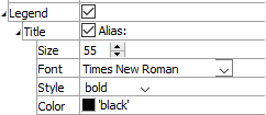
Legend
Set item labeling in the plot legend. See the standard legend control description for details. Beneath Title, the Cable plot item also provides controls in Legend for Shrink, Labels, Map, and Def-Fac.
| Was this helpful? ... | Itasca Software © 2024, Itasca | Updated: Dec 05, 2024 |
