Reinforced Concrete Beam (FLAC3D)
Problem Statement
Note
The project file for this example is available to be viewed/run in FLAC3D.[1] The project’s main data file is shown at the end of this example.
In this example, a concrete beam with dimension of 0.1 m x 0.1 m x 1 m is supported 0.1 m from both ends. Two loads are applied to the top of the beam at points 0.3 m from each end (Points A and B). Three steel bars are installed 0.02 m higher from the base of the beam, each with a length of 0.9 m. Two cases are considered: the bars are modeled as cable elements, or as beam elements. A schematic of the beam is shown in Figure 1. The beam material is modeled using a concrete model, with material properties listed in Table Table #reinforcedconcreteproperties. The steel bars are assumed to have a circular cross-section with a radius of 0.005 m. The steel has a Young’s modulus of 200 GPa and a Poisson’s ratio of 0.3.
Parameter |
Value |
|
|---|---|---|
\(E\) (MPa) |
3 |
.14e4 |
\(\nu\) |
0 |
.18 |
\(f_t^m\) (MPa) |
3 |
.48 |
\(f_t^0\) (MPa) |
3 |
.48 |
\(G_t\) (MN/m) |
40 |
e-6 |
\(l_t\) (m) |
0 |
.0826 |
\(D_t^{half}\) |
0 |
.5 |
\(f_c^m\) (MPa) |
27 |
.6 |
\(f_c^0\) (MPa) |
16 |
.04 |
\(G_c\) (MN/m) |
5690 |
e-6 |
\(l_c\) (m) |
0 |
.0826 |
\(D_c^{peak}\) |
0 |
.4 |
\(f_b^0/f_c^0\) |
1 |
.16 |
\(a_p\) |
0 |
.2 |
\(s_0\) |
0 |
.2 |
The grid in FLAC3D is shown in in Figure 2. The displacement-control method is used, with a fixed velocity applied at Points A and B. By the end of the simulation, these two points will have a total vertical displacement of 1.5e-3 meters. The reaction force (P) at Point A or B is monitored using a FISH function. The vertical displacement (\(\delta\)) at the center of the beam’s base is also tracked.
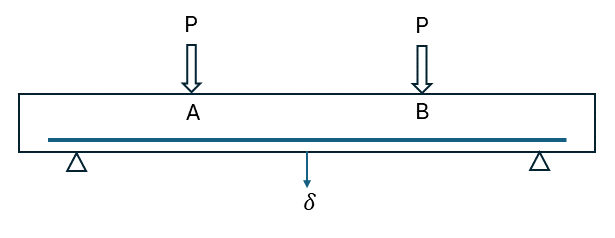
Figure 1: Grid of the model.

Figure 2: Grid of the model.
Case 1: Bars as Cable
Three cables, spaced 0.03 meters apart, are assigned and assumed to have a yield tension force of 0.157 MN, corresponding to a yield strength of 200 MPa. At the cable ends, the links are modified into translational rigid links to simulate the cable bolting effect. Figure 3 shows the maximum shear strain increment, where tension cracks are clearly visible in the beam. Shear failure is observed between the support points and the loading positions. Figure 4 plots the relationship between the reaction force (P) and displacement \(\delta\). As tension cracks develop, the slope of the P vs. \(\delta\) curve gradually flattens. When the shear bands between the supports and loading points become continuous, the hardening curve of P vs. \(\delta\) exhibits brittle behavior, followed by softening due to the combined effects of the concrete and steel. Figure 5 plots the axial forces of the cable elements.
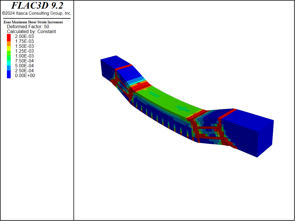
Figure 3: Contour of maximum shear strain increment showing cracks, using cable elements.
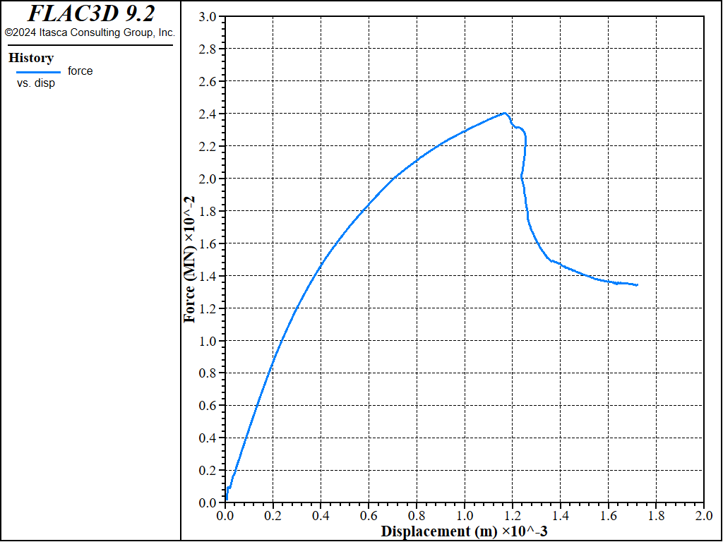
Figure 4: The applied vertical force (P) vs. the displacement at the center of the beam base (\(\delta\)), using cable elements.
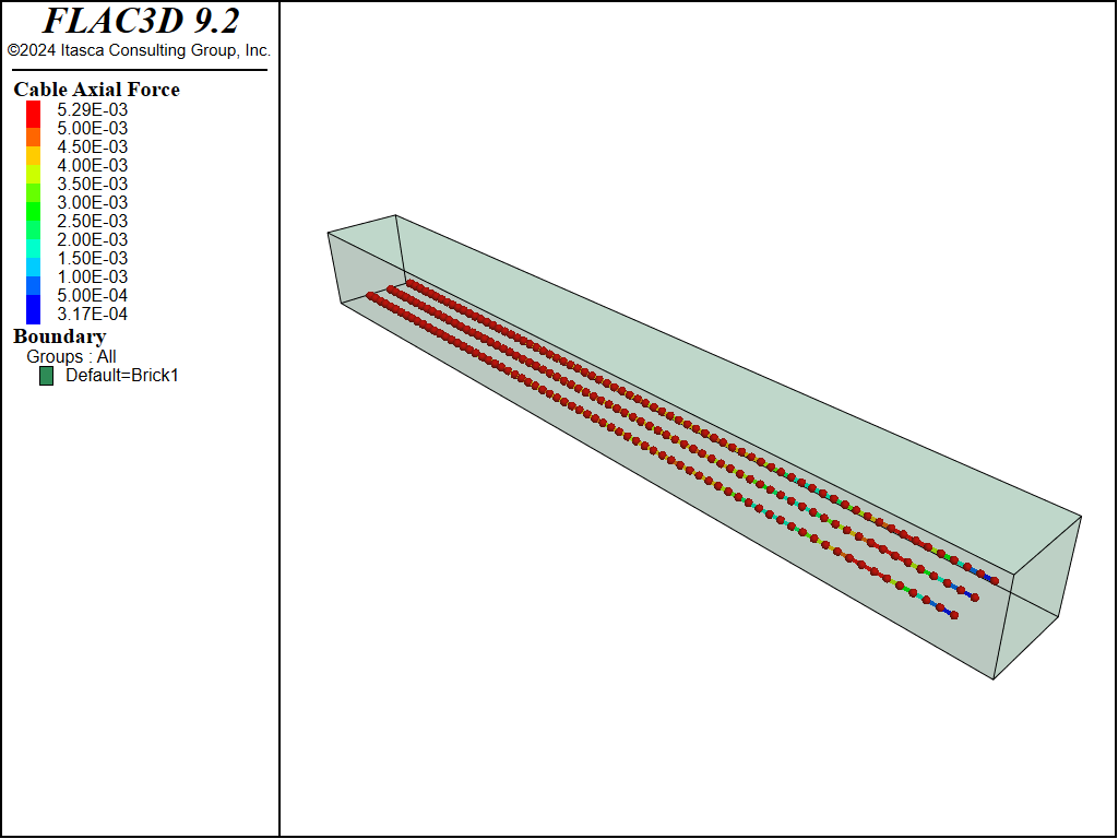
Figure 5: The cable axial forces in the cables, using cable elements.
Case 2: Bars as Beam
Three beams, spaced 0.03 meters apart, are assigned, and this time the elements are assumed to follow the von-Mises material model. A cross-sectional integration layout of (2,2,7) is used. The results are presented in Figure 6 to Figure 8. Overall, this case yields results very similar to the cable model case.

Figure 6: Contour of maximum shear strain increment showing cracks, using beam elements.

Figure 7: The applied vertical force (P) vs. the displacement at the center of the beam base (\(\delta\)), using beam elements.
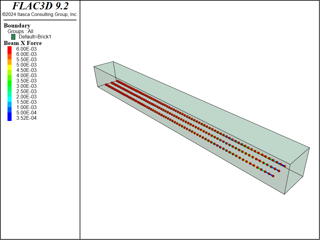
Figure 8: The cable axial forces in the beams.
Data File
reinforcedConcrete-cable.dat
model new
model large-strain off

zone create brick size 10 1 1
zone gridpoint initialize position (0.1,0.1,0.1) multiply
zone densify segments 10 10 10
zone face skin

fish define parameters
    global young = 3.1e4  ; MPa
    global poisson = 0.18
    global ft = 3.48      ; MPa
    global Gt = 40e-6     ; MN/m
    global Lt = 0.0826/10 ; m
    global fc = 27.6      ; MPa
    global ft = 3.48      ; MPa
    global Gc = 5690e-6   ; MN/m
    global Lc = 0.0826/10 ; m
    global kbc0 = 1.16
    global fc0 = 16.04    ; MPa
    global ft0 = 3.48     ; MPa
    global dc = 800       ; dc
    global dt = 3000      ; dt
end
[parameters]
;
zone cmodel assign concrete
zone property young [young] poisson [poisson]
zone property compression-strength [fc] compression-initial [fc0] ...
              compression-energy-fracture [Gc]
zone property compression-length-reference [Lc] compression-d [dc]
zone property tension-strength [ft] tension-initial [ft0] ...
              tension-energy-fracture [Gt]
zone property tension-length-reference [Lt] tension-d [dt]
zone property ratio-biaxial [kbc0] tension-recovery 0.2
zone property dilation 20

structure cable create by-line (0.05, 0.02, 0.02) (0.95, 0.02, 0.02) ...
                       segments 70 group-begin "end1" group-end "end2" group ...
                       "streel" id 1
structure cable create by-line (0.05, 0.05, 0.02) (0.95, 0.05, 0.02) ...
                       segments 70 group-begin "end1" group-end "end2" group ...
                       "streel" id 1
structure cable create by-line (0.05, 0.08, 0.02) (0.95, 0.08, 0.02) ...
                       segments 70 group-begin "end1" group-end "end2" group ...
                       "streel" id 1

structure link attach x rigid y rigid z rigid range group "end1"
structure link attach x rigid y rigid z rigid range group "end2"

structure cable property young 2e5 cross-sectional-area 7.85e-5
structure cable property grout-stiffness 1e6 grout-perimeter 0.0314
structure cable property grout-friction 25 grout-cohesion 100
structure cable property yield-tension 0.0157

model range create "Load1" range position-x 0.29 0.31 position-z 0.1
model range create "Load2" range position-x 0.69 0.71 position-z 0.1
zone gridpoint group "Load1" range named-range "Load1"
zone gridpoint group "Load2" range named-range "Load2"
[global LoadedPts1 = list(gp.list)(gp.isgroup(::gp.list,"Load1"))]
[global LoadedPts2 = list(gp.list)(gp.isgroup(::gp.list,"Load2"))]

fish define load
    load1 = list.sum(gp.force.unbal(::LoadedPts1)->z)
    load2 = list.sum(gp.force.unbal(::LoadedPts2)->z)
    load  = (load1 + load2)/2
end

zone gridpoint fix velocity (0,0,0) range position-x 0.09 0.11 position-z 0
zone gridpoint fix velocity (0,0,0) range position-x 0.89 0.91 position-z 0
zone gridpoint fix velocity-z -1e-8 range named-range "Load1"
zone gridpoint fix velocity-z -1e-8 range named-range "Load2"

zone mechanical damping combined

history interval 500
zone history name 'disp' displacement-z position 0.5 0.05 0
fish history name 'force' load

;model results interval mech 500
model cycle 150000

model save 'reinforcedConcrete-cable'
reinforcedConcrete-beam.dat
model new
model large-strain off

zone create brick size 10 1 1
zone gridpoint initialize position (0.1,0.1,0.1) multiply
zone densify segments 10 10 10
zone face skin

fish define parameters
    global young = 3.1e4  ; MPa
    global poisson = 0.18
    global ft = 3.48      ; MPa
    global Gt = 40e-6     ; MN/m
    global Lt = 0.0826/10 ; m
    global fc = 27.6      ; MPa
    global ft = 3.48      ; MPa
    global Gc = 5690e-6   ; MN/m
    global Lc = 0.0826/10 ; m
    global kbc0 = 1.16
    global fc0 = 16.04    ; MPa
    global ft0 = 3.48     ; MPa
    global dc = 800       ; dc
    global dt = 3000      ; dt
end
[parameters]
;
zone cmodel assign concrete
zone property young [young] poisson [poisson]
zone property compression-strength [fc] compression-initial [fc0] ...
              compression-energy-fracture [Gc]
zone property compression-length-reference [Lc] compression-d [dc]
zone property tension-strength [ft] tension-initial [ft0] ...
              tension-energy-fracture [Gt]
zone property tension-length-reference [Lt] tension-d [dt]
zone property ratio-biaxial [kbc0] tension-recovery 0.2
zone property dilation 20

structure beam create by-line (0.05, 0.02, 0.02) (0.95, 0.02, 0.02) ...
                      segments 70 group-begin "end1" group-end "end2" group ...
                      "streel" id 1
structure beam create by-line (0.05, 0.05, 0.02) (0.95, 0.05, 0.02) ...
                      segments 70 group-begin "end1" group-end "end2" group ...
                      "streel" id 1
structure beam create by-line (0.05, 0.08, 0.02) (0.95, 0.08, 0.02) ...
                      segments 70 group-begin "end1" group-end "end2" group ...
                      "streel" id 1

structure beam cmodel assign von-mises
structure beam cmodel plastic-integration cross-section ...
                      circular 0.005 layout 2 2 7
structure beam property direction-y (0,1,0) young 2e5 poisson 0.3 ...
                        strength-yield 200

model range create "Load1" range position-x 0.29 0.31 position-z 0.1
model range create "Load2" range position-x 0.69 0.71 position-z 0.1
zone gridpoint group "Load1" range named-range "Load1"
zone gridpoint group "Load2" range named-range "Load2"
[global LoadedPts1 = list(gp.list)(gp.isgroup(::gp.list,"Load1"))]
[global LoadedPts2 = list(gp.list)(gp.isgroup(::gp.list,"Load2"))]

fish define load
    load1 = list.sum(gp.force.unbal(::LoadedPts1)->z)
    load2 = list.sum(gp.force.unbal(::LoadedPts2)->z)
    load  = (load1 + load2)/2
end

zone gridpoint fix velocity (0,0,0) range position-x 0.09 0.11 position-z 0
zone gridpoint fix velocity (0,0,0) range position-x 0.89 0.91 position-z 0
zone gridpoint fix velocity-z -1e-8 range named-range "Load1"
zone gridpoint fix velocity-z -1e-8 range named-range "Load2"

zone mechanical damping combined

history interval 500
zone history name 'disp' displacement-z position 0.5 0.05 0
fish history name 'force' load

;model results interval mech 500
model cycle 150000

model save 'reinforcedConcrete-beam'
Endnote
| Was this helpful? ... | Itasca Software © 2024, Itasca | Updated: Dec 05, 2024 |
