Pressurized Cylindrical Cavern
Problem Statement
Note
View this project in FLAC3D:
- Pick “ExampleApplications”
- Pick “PressurizedCylindrical…”
- Select “Pressurized… .f3dprj” to load
The project’s main data file is shown at the end of this example.
A pressurized cylindrical cavern is excavated in bedded salt.[*] The salt bed is sandwiched between 15-m thick layers of a stiff elastic material (Material 2) above and below the salt bed. The far-field in-situ state of stress is anisotropic. The objective of the analysis is to determine the closure of the cavern and the change in the state of stress in Material 2 along the interface with the salt.
The salt is 60 m thick and is assumed to be infinite in horizontal extent. The cylindrical cavern has a diameter of 90 m, a height of 30 m, and is located in the middle of the salt bed (i.e., a 15 m layer of salt exists between the top and bottom of the cavern and the stiff elastic layers).
The far-field in-situ state of stress is (compressive stresses are negative):
σxx = -56 MPa (east-west)
σyy = -28 MPa (north-south)
σzz = -35 MPa (vertical)
The salt exhibits a creep behavior that is characterized by a single-component power law. The rock mass properties for the salt, the stiff elastic layer (Material 2), and the overburden rock (Material 3) are summarized in Table 1.
| Salt | Material 2 | Material 3 | |
|---|---|---|---|
| Elastic Properties: | |||
| Young’s Modulus in psi | 10e6 | 30e6 | 10e6 |
| Young’s Modulus in MPa | 68.9475 | 206.8428 | 68.9475 |
| Poisson’s Ratio | 0.3 | 0.3 | 0.3 |
| Creep Properties: | |||
| A | 3.9 × 10⁻⁷ MPa-4.9 yr-1 | ||
| n | 4.9 |
Modeling Procedure
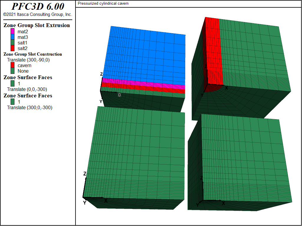
The FLAC3D model is constructed using the 2D Extruder pane with the z-axis as the axis of
rotation of the cylindrical cavern. The xy-plane is a plane of symmetry because of the problem
geometry and anisotropic stress state. Figure Figure #cavern-grid0 shows the FLAC3D grid for this
problem. Only one-eighth of the cavern is modeled because of the symmetry conditions. Three or the four
meshes in the figure displays various groups assigned interactively in the extruder. The last mesh in the
lower right shows the face groups assigned with the zone face skin command.
The x = 0, y = 0, and z = 0 planes are symmetry planes and have rollered boundary conditions. The far-field boundary at x = 250 m is fixed in the x-direction, and the boundary at y = 250 m is fixed in the y-direction. A vertical stress of -35 MPa is applied at the top boundary (z = 250 m). The model is subjected to an initial in-situ stress-state of σxx = -56 MPa, σyy = -28 MPa, σzz = -35 MPa. A gravitational stress-gradient is not considered in this analysis.
The cavern is to be excavated over a period of 0.1 year. The excavation is simulated by reducing the normal pressure exerted along the cavern periphery from the in-situ stress value to a value of 7 MPa after 0.1 year. The pressure is then held constant at 7 MPa for a total time of 1 year.
This analysis is divided into three stages.
In the first stage, the model is brought to a pre-excavation stress state
that is considered to be compatible with the far-field in-situ stresses and the creep behavior assumed for the salt.
In the second stage the cavern is excavated by using a table,
load, to reduce the pressure at the cavern wall linearly from the initial stress state to 7 MPa in 0.1 year.
Finally in the third stage, the creep response #fred_bob of the model is followed for a total time of 1 year.
Discussion
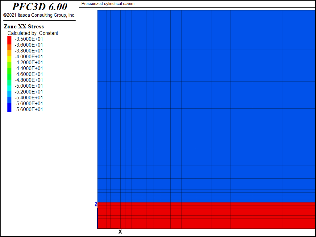
The salt will creep under the imposed anisotropic stress field, even without the presence of an excavation. This is because the creep rate in the power-law formulation is a function of deviatoric stress. For the first stage, in order to approach a stress state that is reasonably compatible with both the imposed stress conditions and the creep behavior, initial isotropic stresses of -35 MPa are specified for the zones representing the salt bed. As the contours of σxx in Figure 2 show, there is a stress discontinuity across the salt and Material 2 interface.
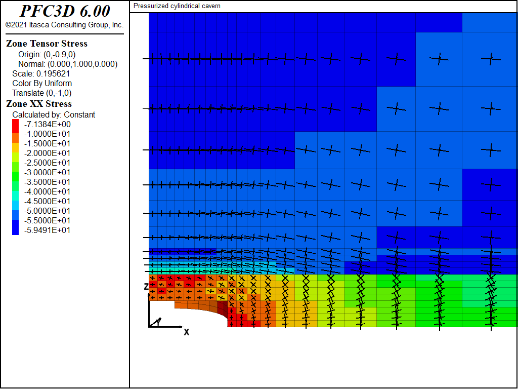
In the second stage, the effect of the excavation on the stresses within the stiff layer, Material 2, can be seen in Figure 3. This figure includes a plot of σxx contours and principal stress tensors on a vertical plane through the cavern at 0.1 year. The plot for σxx contours and principal stresses after 1 year of creep is also shown in Figure 4. The development of higher horizontal stresses across Material 2 directly above the excavation is observed in Figure 3; this stress is reduced with creep, as evidenced in Figure 4.
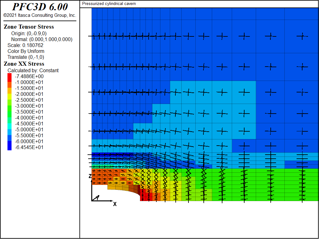
Figure 3: Contours of σxx on a vertical plane through the cavern after 0.1 year (at the end of excavation).
Figure 5 shows a history of displacements of three locations around the cavern periphery after 1 year. Figure 6 and Figure 7 show displacement vectors on a vertical plane and a horizontal plane, respectively, through the center of the cavern. These three figures indicate that the greatest displacements are in the horizontal (x- and y-) direction. After 1 year, a maximum of approximately 0.41 m displacement occurs in the horizontal (negative x- and y-) direction, and approximately 0.05 m displacement occurs in the vertical (negative z-) direction.
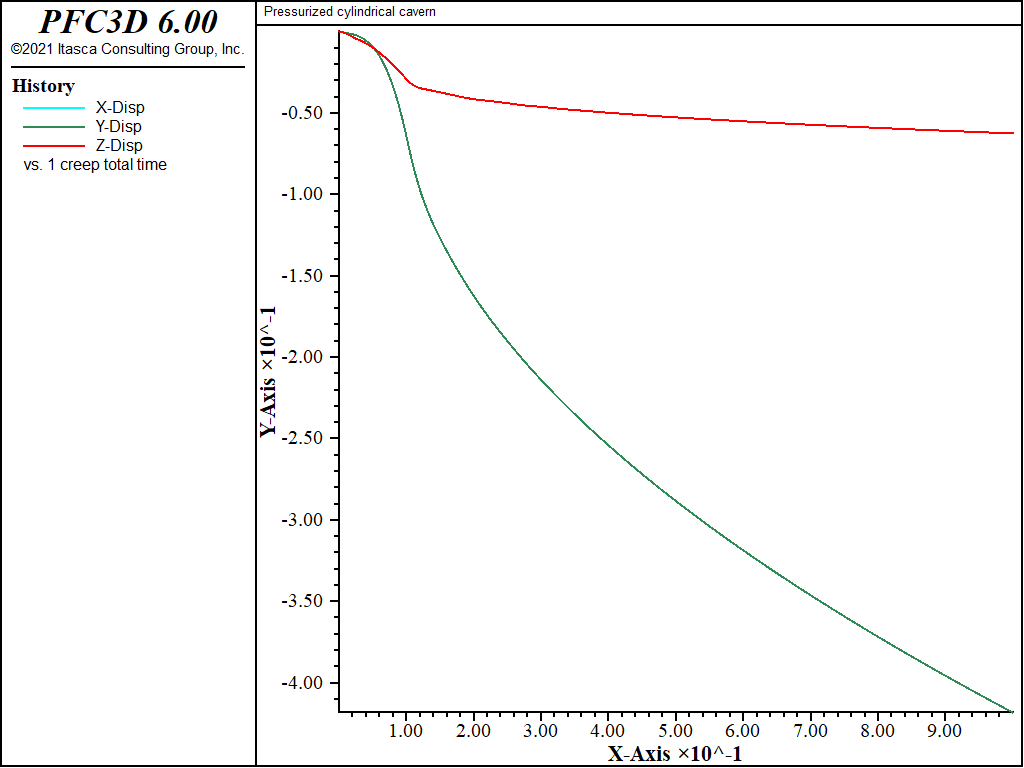
Figure 5: Displacement histories for a 1-year period (post-excavation) at three locations around the cavern periphery: x-displacement at cavern East; y-displacement at cavern North; z-displacement at cavern roof.
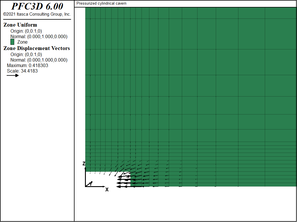
Figure 6: Displacement vectors on the vertical plane through the cavern center at 1 year (post-excavation).
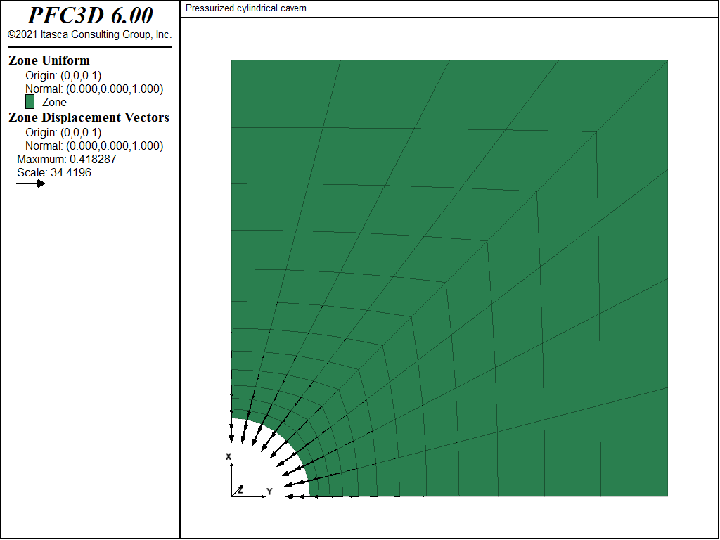
Figure 7: Displacement vectors on the horizontal plane through the cavern center at 1 year (post-excavation).
Endnote
| [*] | This problem is derived from information furnished by Dr. Marc C. Loken, RE/SPEC Inc., Rapid City, South Dakota. |
Data File
;-------------------------------------------------------------------
;                Creep of Cylindrical Cavern
;                anisotropic in-situ stress field
;                (units: m, MPa, year)
;-------------------------------------------------------------------
model new
model largestrain off
fish automatic-create off
model title 'Pressurized cylindrical cavern'
model configure creep
; create model (quarter-symmetry), created interactively
; and exported from State Pane
; Also assigns groups to salt layers, mat1 and mat2, cavern,
; and cavern walls + floor
call 'geometry'
zone generate from-extruder
zone face skin ; Label model boundaries
; Assign material model and properties
zone cmodel assign power range group 'salt1' or 'salt2'
zone cmodel assign elastic range group 'mat2'
zone cmodel assign elastic range group 'mat3'
; material properties - E = 10e6 or 30e6 psi
; converted to MPa by factor 0.00689476
zone property young [10e6*0.00689476] poisson 0.3 ...
     range group 'salt1' or 'salt2'
zone property constant-1=3.9e-7 exponent-1=4.9 ...
     range group 'salt1' or 'salt2'
zone property young [30e6*0.00689476] poisson 0.3 range group 'mat2'
zone property young [10e6*0.00689476] poisson 0.3 range group 'mat3'
; boundary and initial conditions
zone face apply velocity-normal 0 range group 'East' or 'West'
zone face apply velocity-normal 0 range group 'North' or 'South'
zone face apply velocity-normal 0 range group 'Bottom'
zone face apply stress-normal -35 range group 'Top'
zone initialize stress xx -56 yy -28 zz -35
zone initialize stress xx -35 yy -35 zz -35 range group 'salt1' or 'salt2'
model creep active off
model solve ratio-local 1e-4
zone gridpoint initialize velocity (0,0,0)
model save 'cavern-init'
; excavate cavern
zone cmodel assign null range group 'cavern' group 'salt1'
table 'load' add (0,-35) (0.1,-7) (1.0,-7)
zone face apply stress-normal 1 table 'load' time creep ...
     range group 'wall' or 'floor'
; histories
model history name 'ctime' creep time-total
zone history name 'xclose' displacement-x position (45, 0, 0)
zone history name 'yclose' displacement-y position ( 0,45, 0)
zone history name 'zclose' displacement-z position ( 0, 0,15)
;
zone gridpoint initialize displacement (0,0,0)
model creep active on
model creep time-total = 0.0
model creep timestep starting 1.0e-5
model creep timestep minimum 1.0e-5
model creep timestep auto
; solve for 0.1 yr excavation
model creep timestep maximum 5.0e-5
model solve time-total 0.1
model save 'cavern-010'
; solve for 1 yr of creep
model creep timestep maximum 1.2e-4
model solve time-total 1.0
model save 'cavern-100'
| Was this helpful? ... | PFC 6.0 © 2019, Itasca | Updated: Nov 19, 2021 |

