Creation of a Synthetic Rock Mass (SRM) Specimen
| Tutorial Resources | |
|---|---|
| Data Files | Project: Open {“FracturedRock.p2prj” in PFC2D; “FracturedRock.p3prj” in PFC3D} [1] |
Introduction
Rock masses are complex systems composed of a rock matrix that may have heterogeneous material properties, often riddled with discontinuities (e.g., fractures, joints, faults, etc.). Failure in such systems may occur in the matrix, along discontinuities at both locations. PFC has been successfully used to study the mechanical behavior of such systems due to the development of the smoothjoint contact model ([Pierce2012a]). The modeling approach consists of superimposing fracture information (i.e., fracture geometries and properties) onto a bonded-particle model (BPM, [Potyondy2015d]). The BPM is used to model intact rock, and the mechanical behavior of the fractures is introduced by modifying the contact models at contacts intercepting fractures. As PFC models are inherently discrete, failure can occur both in intact BPM regions and along the fracture planes. The determination of rock mass properties from such a configuration has been termed the Synthetic Rock Mass (SRM) methodology.
With the addition of the discrete fracture network logic, the modeling steps required to perform such a study are greatly simplified in PFC 6.0, as demonstrated by this tutorial.
An intact BPM model is created using the linear parallel bond contact model. To build a full-scale model efficiently, the brick logic is employed, whereby a small model is created in periodic space and subsequently assembled into a full-scale model. A DFN is finally generated and used to assign smoothjoint contact models to contacts intercepting fractures. Support for creating bonded-particle models is provided by the material-modeling support package, but this package is not used herein because it does not yet support the creation of a material in periodic space.
PFC2D Model
The file “doall.p2dvr” sequentially calls other data files to perform each step of the modeling process. This strategy can be used to effectively manage multistep simulations.
Building the Intact Rock
Creation of the intact specimen is performed in two steps. A small system is first equilibrated in periodic space. This system is used as a brick and assembled to create a larger, full-scale model.
The file make_brick.p2dat is used to create the elementary brick.
; fname: make_brick.p2dat
;
; create a brick in periodic space
;===========================================================================
model new
model domain extent -2.0 2.0 condition periodic
contact cmat default model linear property kn 1e5
model random 10001
ball distribute porosity 0.08 radius 1.0 1.6 res 0.025
ball attribute density 2500.0 damp 0.7
model cycle 1000 calm 10
model mechanical timestep scale
model solve
model calm
brick make id 1
brick export id 1 skip-errors
return
;===========================================================================
; eof: make_brick.p2dat
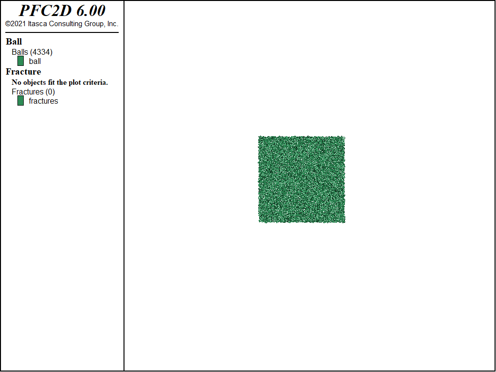
The goal at this stage is to build a dense and well-connected assembly. The default slots of the CMAT are filled with the linear contact model with specified normal stiffness. Balls are created using the ball distribute command to match a target porosity, and density and local damping attributes are set. The system is then solved to equilibrium (first using the model cycle command with the calm keyword, then the model solve command). Figure 1 shows the brick that is exported as a binary file (see the brick export command) for later use.
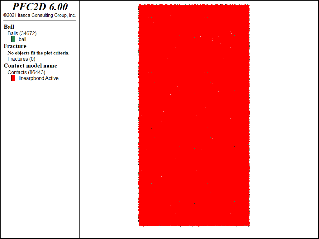
The brick is assembled using the commands in “make_intact.p2dat”. In this example, the brick is replicated twice in the horizontal direction and four times in the vertical direction, for a final model size of 8.0 by 16.0 length-units, comprising approximately 35,000 balls. Note that importing the brick does not modify the default slots of the CMAT. As a result, they are modified by assigning the linear parallel bond contact model with lin_mode = 1. This property sets the normal force calculation mode of the linear component to incremental versus absolute. The deformability method is used to set the micro-properties to meet a target Young’s modulus for the linear portion of the contact model. The CMAT is applied so that all contacts are assigned the updated contact model, and the contact forces/moments are nulled. Nulling the contact forces/moments and changing the normal force calculation to incremental mode removes the built-in stresses and may be desirable in certain circumstances. Finally, all contacts between balls that overlap are bonded with the contact method command, and the parallel bond properties are set accordingly. One would likely not want to enter the bond method in the CMAT, since this would result in attempting to bond all subsequently created contacts. Figure 2 shows the intact specimen.
; fname: make_intact.p2dat
;
; assemble a brick in a full-scale model and install the linear parallel
; bond contact model
;===========================================================================
model new
model domain extent -4.0 4.0 -8.0 8.0
brick import id 1
brick assemble id 1 origin -4.0 -8.0 size 2 4
contact cmat default model linearpbond method deformability emod 60e9 ...
                           kratio 2.5 property fric 0.5 lin_mode 1
contact cmat apply
ball attribute force-contact multiply 0.0 moment-contact multiply 0.0
contact method bond gap 0.0 pb_deformability emod 60e9 kratio 2.5
contact property pb_ten 1e8 pb_coh 5e7 pb_fa 20.0
model save 'intact'
return
;===========================================================================
; eof: make_intact.p2dat
Superimposing Fractures
The file “make_fractured.p2dat” is used to superimpose fractures onto the intact BPM.
; fname: make_fractured.p2dat
;
; restore an intact BPM - generate a DFN and install the smoothjoint
; contact model at contacts intercepted by the fractures
;===========================================================================
model restore 'intact'
model random 10001
fracture template create 'test' size power-law 3 size-limits 1 100
fracture generate dfn 'fractures' template 'test' ...
         generation-box -4 4 -8 8 p10 1.5 begin (0,-8) end (0,8)
fracture combine angle 30.0 distance 1.0 merge
fracture combine angle 40.0 distance 1.0 merge
fracture contact-model model 'smoothjoint' install
model save 'fractured'
return
;===========================================================================
; eof: make_fractured.p2dat
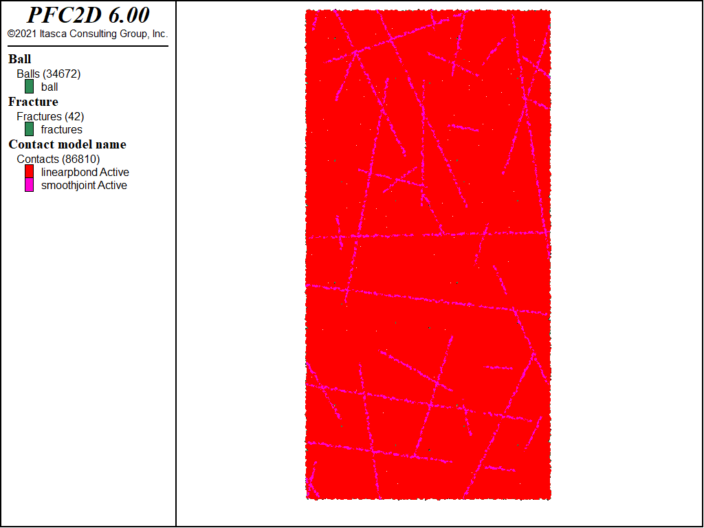
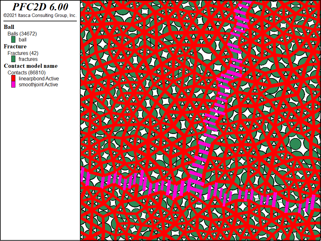
A statistical DFN model is defined using the fracture template create command. In this case, fractures follow a power-law size distribution with exponent -3 and length limits of 1 to 100 units. A DFN is one realization using the DFN template as the statistical model. One DFN is generated (see the fracture generate command) with stop criterion based on the fracture frequency, or P10, along a vertical line. This DFN is altered using the fracture combine command to merge fractures that have similar orientations and are spatially close to one another in space. This operation may be desirable, because the number of fractures prior to the merge procedure may be unnecessarily high. Finally, the fracture contact-model model command is used to install the smoothjoint contact model in contacts intersecting the fractures. Note that any contact model could be used. Figure 3 shows the final system, and Figure 4 shows a detail of the system.
PFC3D Model
Data files to build a similar model with PFC3D are also provided:
The steps are identical to those in the PFC2D model and are not discussed here. Figure 5 shows the final 3D system with balls (left), parallel-bonds and smoothjoint contacts (middle), and the DFN (right).
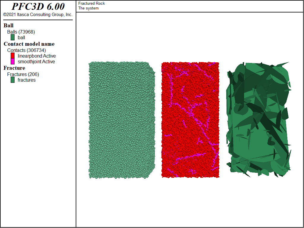
Figure 5: The fractured specimen in 3D: balls (left), parallel-bonds and smoothjoint contacts (middle) and the DFN (right).
Discussion
This tutorial demonstrates use of the brick logic to efficiently create a large-scale BPM. In addition, steps to generate and simplify a DFN are provided. Contacts intersecting fractures are assigned the smoothjoint contact model, and their properties are set. The resulting SRM specimen is in a state for further testing to determine its strength characteristics.
References
| [Pierce2012a] | Pierce, M.E., and C. Fairhurst. “Synthetic Rock Mass Applications in Mass Mining,” in Harmonising Rock Engineering and the Environment (Proc. 12th ISRM Int. Congress, Beijing, China, October 2011), pp. 109-14, Q. Qian and Y. Zhou, eds., ISBN 978-0-415-80444-8, London: Taylor & Francis Group (2012). |
| [Potyondy2015d] | Potyondy, D. O. “The Bonded-Particle Model as a Tool for Rock Mechanics Research and Application: Current Trends and Future Directions,” Geosystem Engineering, 18(1), 1–28 (2015), DOI:10.1080/12269328.2014.998346. |
Endnote
| [1] | These may be found in PFC3D under the “tutorials/fractured_rock” folder in the Examples dialog ( on the menu). If this entry does not appear, please copy the application data to a new directory. (Use the menu commands . See the “Copy Application Data” section for details.) |
⇐ Data Files for “Slip on a Fault”
Tutorial |
Data Files for “Creation of a Synthetic Rock Mass (SRM) Specimen” Tutorial ⇒
| Was this helpful? ... | PFC 6.0 © 2019, Itasca | Updated: Nov 19, 2021 |

