Using the CMAT
| Tutorial Resources | |
|---|---|
| Data Files | Project: Open “UsingTheCMAT.p2prj” in PFC2D [1] |
Introduction
Which contact model should be installed when a contact forms? The answer to this question, which will determine the constitutive mechanical behavior of a PFC model, is a fundamental one and is intimately tied to the specifics of each PFC model. Nobody but the modeler can answer it, and PFC itself cannot make any generic assumption [2]. Instead, PFC will use the null model contact model by default and therefore, the user is required to explicitly specify which contact model(s) should be used in each PFC model.
The Contact Model Assignment Table (CMAT) has been introduced in PFC to allow users to specify this information. The CMAT is a very generic tool that can handle both built-in contact models and user-defined contact models. Furthermore, with just a few command lines, it can be used to build simple systems as well as complex ones (i.e., with several contact models and/or heterogeneous mechanical properties).
This tutorial illustrates the main features of the CMAT and how to use them appropriately. The CMAT is queried any time a new contact is created in order to determine which contact model should be installed at that specific contact.
Numerical Models
The numerical models used in this tutorial are voluntarily simple. A container (modeled with a wall) is filled with a collection of balls, and cycles are performed to bring the model to equilibrium under various loading conditions.
The discussion below focuses on the features that are relevant to the CMAT. For additional information about other aspects of the model (creation of the assembly), please refer to the tutorial “Balls in a Box.”
Using the Default Slots
As described here, the CMAT consists of an ordered set of (optional) slots along with a default slot for each contact type. In many situations where the constitutive behavior is homogeneous across the system, setting the default slots of the CMAT suffices.
In “cmat1.p2dat”, the default slots of the CMAT are filled with the linear contact model, with a normal stiffness \(k_n\)=1.0e6 and a normal critical damping ratio \(\beta_n\)=0.2 [3]. This is achieved with the command
; set ALL the default slots of the CMAT
contact cmat default model linear property kn 1e6 dp_nratio 0.2
Note that the contact cmat default command will automatically apply to all the default slots unless a type is specified. The system constructed here will comprise both ball-ball and ball-facet contacts; all of these contacts will use an identical linear model with \(k_n\)=1.0e6 and \(\beta_n\)=0.2. Figure 1 shows the final state of the system after balls have settled on the floor of the box under gravity.
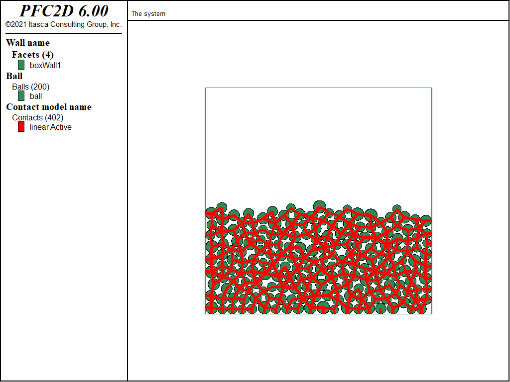
Figure 1: The final system constructed by “cmat1.p2dat”.
The data file “cmat2.p2dat” builds a system that is similar to the one above, except that two different contact models are used instead of one. Contacts between balls are assigned the Hertz Model contact model, while the contacts between balls and wall facets retain the linear contact model. Since this distinction is based only on the type of the contacts, the default slots of the CMAT again suffice:
; set different contact models for the ball-ball and ball-facet contact types
contact cmat default type ball-ball ...
                   model hertz      ...
                   property hz_shear 30e9 hz_poiss 0.3  ...
                            fric 0.25                   ...
                            dp_nratio 0.2

contact cmat default type ball-facet ...
                   model linear      ...
                   property kn 1e6 dp_nratio 0.2
Figure 2 shows the final state of the system; the two different contact models have been appropriately assigned during the course of the simulation.
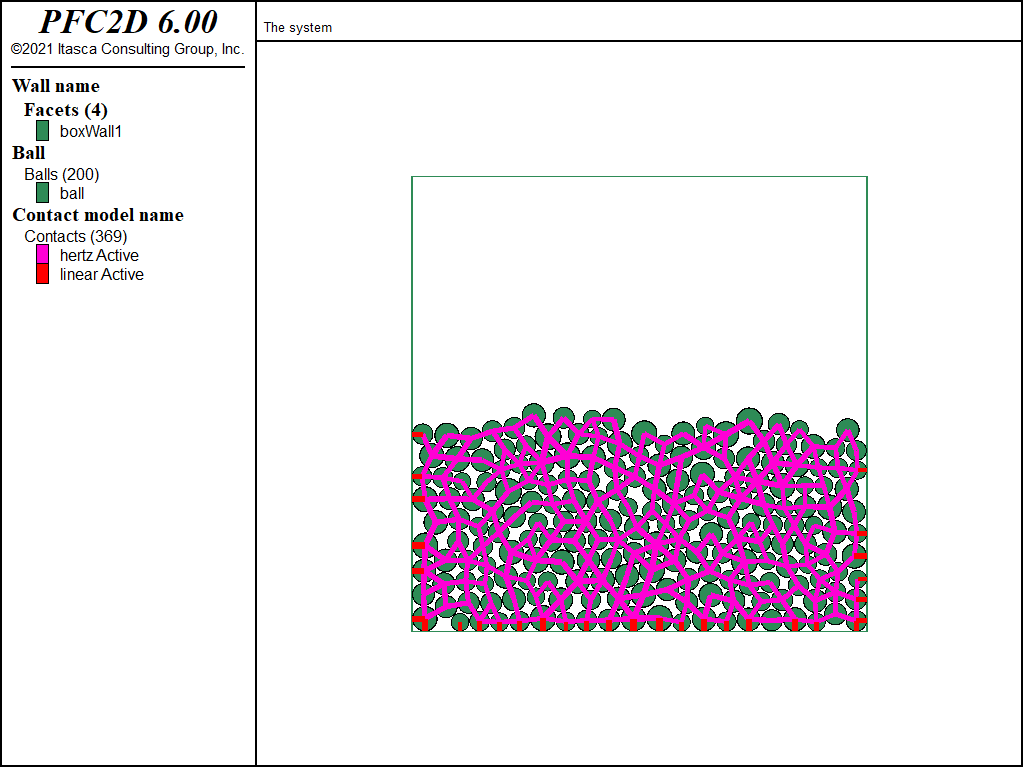
Figure 2: The final system constructed by “cmat2.p2dat”. Two distinct contact models, which depend on the contact type, are used in this model.
Using Additional Slots
Further complexity is introduced in the model with the data file “cmat3.p2dat”, where the intent is to model a mix of balls made of steel and glass using the hertz contact model. In this case, two different groups of balls are created to represent the two materials and optional slots are registered in the CMAT to control the mechanical properties used by the hertz contact model depending on the groups of the two contacting pieces.
contact cmat add 1 model hertz                          ...
                 property hz_shear 30e9 hz_poiss 0.3    ...
                          fric 0.25                     ...
                          dp_nratio 0.2                 ...
           range group 'glass' matches 2

contact cmat add 2 model hertz                          ...
                 property hz_shear 70e9 hz_poiss 0.3    ...
                          fric 0.05                     ...
                          dp_nratio 0.2                 ...
           range group 'steel' matches 2

contact cmat default type ball-ball                     ...
                   model hertz                          ...
                   property hz_shear 50e9 hz_poiss 0.3  ...
                           fric 0.05                    ...
                           dp_nratio 0.2

contact cmat default type ball-facet                    ...
                   model linear                         ...
                   property kn 1e6 dp_nratio 0.2
The commands listed above define three slots related to ball-ball contacts.
- Slot 1 controls the assignment of the hertz contact model whose properties are consistent with glass-glass interactions. This is accomplished using the glass group identifier.
- Slot 2 controls the assignment of the hertz contact model whose properties are consistent with steel-steel interactions. This is accomplished using the steel group identifier.
- The default slot for ball-ball contacts controls the assignment of the hertz contact model whose properties are consistent with glass-steel interactions.
Whenever a contact is created during the course of the simulation, the CMAT is processed as follows: First, the two optional slots are visited in order of increasing index number. Then, if the contact does not fulfill any of the ranges of the optional slots, the default slot corresponding to the type of contact being created is used. Once a contact is created in the present model, slot 1 of the CMAT is inspected to determine whether the corresponding contact model should be used based on the assignment criteria (i.e., the two balls have group identifier glass). If the assignment criteria are not met, slot 2 of the CMAT is inspected in a similar fashion. If all slots of the CMAT have been visited and no suitable contact model has been identified, the contact model held in the default slot of the CMAT is assigned.
Note that the range selection used in this example is based on groups defined for the contacting pieces. The Group logic is a generic utility that can be used to identify multiple instances of a same-model component. Groups can be assigned to balls, walls, and clumps, as well as facets or pebbles, and even contacts. However, it is often useful to filter contacts based on the groups assigned to the contacting pieces instead of using groups defined for the contacts themselves, as illustrated in the present case. To this effect, the match keyword of the group range element can be used.
Figure 3 shows the final state of the system. Balls are colored according to their group, and the contacts are colored by the value of the shear modulus property hz_shear (only contacts with a hertz model are displayed). The different contact model properties have been assigned appropriately during the course of the simulation.
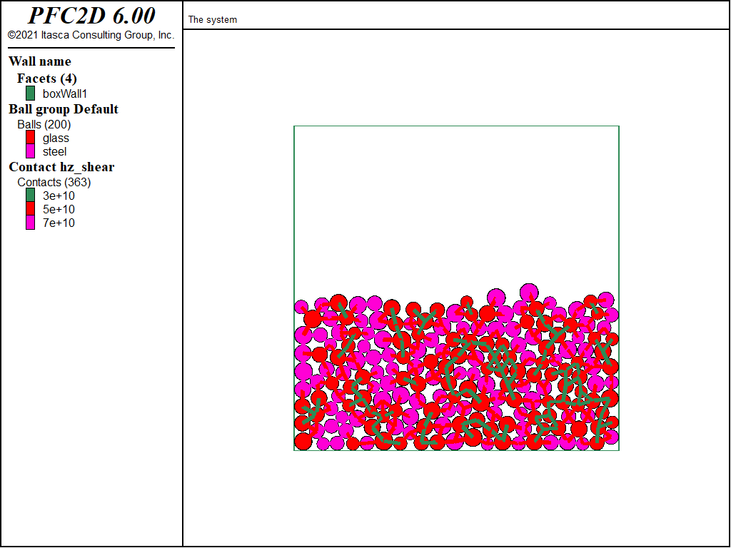
Figure 3: The final system constructed by “cmat3.p2dat”. Balls colored by group (steel and glass) and contacts colored by value of the shear modulus property hz_shear.
Property Inheritance
The example discussed above illustrates how optional slots in the CMAT can be used to specify heterogeneity in contact model properties. Another possibility is to use property inheritance, as illustrated below.
Among all the properties of a contact model, a restricted set may be inherited from properties defined for the contacting pieces. The set of inheritable properties depends on the specific implementation of each contact model, and the Properties table included in each built-in contact model description contains a column that indicates, for each property, whether it can be inherited or not from surface properties (refer to the “Contact Model Framework” section for further details). In “cmat4.p2dat”, the ability of the hertz contact model to inherit the shear modulus \(G\), Poisson’s ratio \(\nu\), and friction coefficient \(\mu\) is used. Instead of using optional slots in the CMAT, where all contact model properties are specified, as done in “cmat3.p2dat”, only the default slots of the CMAT are specified, and inheritable properties are defined at the balls.
contact cmat default type ball-ball         ...
                   model hertz              ...
                   property dp_nratio 0.2

contact cmat default type ball-facet               ...
                   model linear                    ...
                   property kn 1e6 dp_nratio 0.2

ball property 'hz_shear' 30e9 'hz_poiss' 0.3 'fric' 0.25 ...
     range group 'glass'

ball property 'hz_shear' 70e9 'hz_poiss' 0.3 'fric' 0.05 ...
     range group 'steel'
With the commands listed above, whenever a contact forms during the simulation:
- the linear contact model, with a linear stiffness \(k_n\)=106 and a normal critical damping ratio \(\beta_n\)=0.2, is retained for ball-facet contacts; and
- the hertz contact model, with a normal critical damping ratio \(\beta_n\)=0.2, is installed at ball-ball contacts.
The values of the shear modulus \(G\), Poisson’s ratio \(\nu\), and friction coefficient \(\mu\) for each ball-ball contact is not directly specified in the CMAT. Instead, these properties are defined at the balls, and corresponding contact model properties are derived from the ball properties when the contact is created. Refer to the hertz model property inheritance section for details on the derivation of contact model properties from piece properties for the hertz contact model.
Practically, the resulting PFC model (shown in Figure 4) is identical to the model previously discussed (Figure 3), but in the present model, only the default slots of the CMAT have been used. Property inheritance has been used to derive contact model properties in this case. Note that the value of the normal critical damping ratio has been set to be the same for all ball-ball contacts. Since this later property cannot be inherited from piece properties, optional slots in the CMAT would have been required if different values were to be used depending on the groups of the contacting balls.
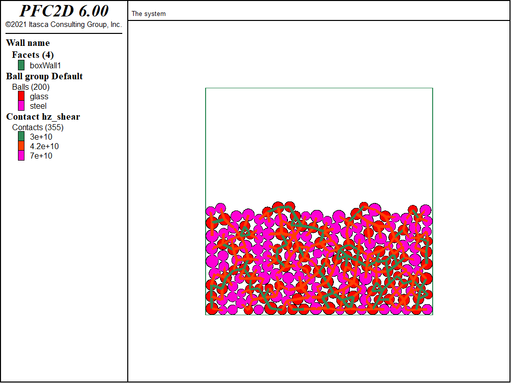
Figure 4: The final system constructed by “cmat4.p2dat”. Balls colored by group (steel and glass), and contacts colored by value of the shear modulus property hz_shear.
Modifying Existing Contacts
All the examples above have discussed different ways of specifying the CMAT to control which contact model (and which properties) should be assigned to newly created contacts during cycling. Another action that is often desired when constructing a PFC model is to modify existing contacts (either to entirely override the existing contact model or to modify only select properties).
The data file “cmat5.p2dat” illustrates two strategies that may be used to modify existing contacts:
- modify the CMAT and issue a
contact cmat applycommand to reset contact models; and - use contact commands to modify select contacts.
The objective is to modify the state produced by “cmat3.p2dat”, i.e., a model with glass and steel balls settled under gravity in a container, and install a linear parallel-bond contact model to all contact between glass balls. The resulting model could represent a system where glass-glass contacts have been sintered through a thermal or chemical process.
The first possibility is exercised with the following commands:
contact cmat modify 1 model linearpbond                        ...
                    method deformability    emod 1e6 krat 0.5  ...
                           pb_deformability emod 1e6 krat 0.5  ...
                    property fric 0.25 dp_nratio 0.2           ...
                           pb_ten 1e8 pb_coh 1e8 pb_fa 30.0

; apply the CMAT - every contact existing in the model will be processed
; and a new contact model will be installed. Note that all information in the
; existing contact model will be lost when it is replaced by a new contact model.
contact cmat apply
contact method bond
In this case, the first slot of the CMAT is modified to use a linear parallel-bond contact model with relevant properties and the contact cmat apply
command is issued. Recall that the first slot of the CMAT was defined in “cmat3.p2dat” to apply to contacts between glass balls.
The state of the system after execution of the contact cmat apply command is shown in Figure 5. On the left-hand side, the balls
(colored by groups) are displayed, as well as the contacts that are colored by the name of their contact model. As expected, three contact models coexist in this model: the linear contact
model at ball-facet contacts, the hertz contact model for contacts involving at least one steel ball, and the linear parallel-bond contact model for contacts between glass balls.
However, it is important to note that the contact cmat apply command was applied to all the existing contacts; all the contacts have been processed and new contact
models have been reassigned based on the current specifications in the CMAT. All previous information stored in the contact models has therefore been reset. For instance, the
remaining hertz contacts colored by the current value of the hertz force are shown on the right-hand side of Figure 5. Because the contact models
have just been reassigned, the current force is equal to its default initial null value.
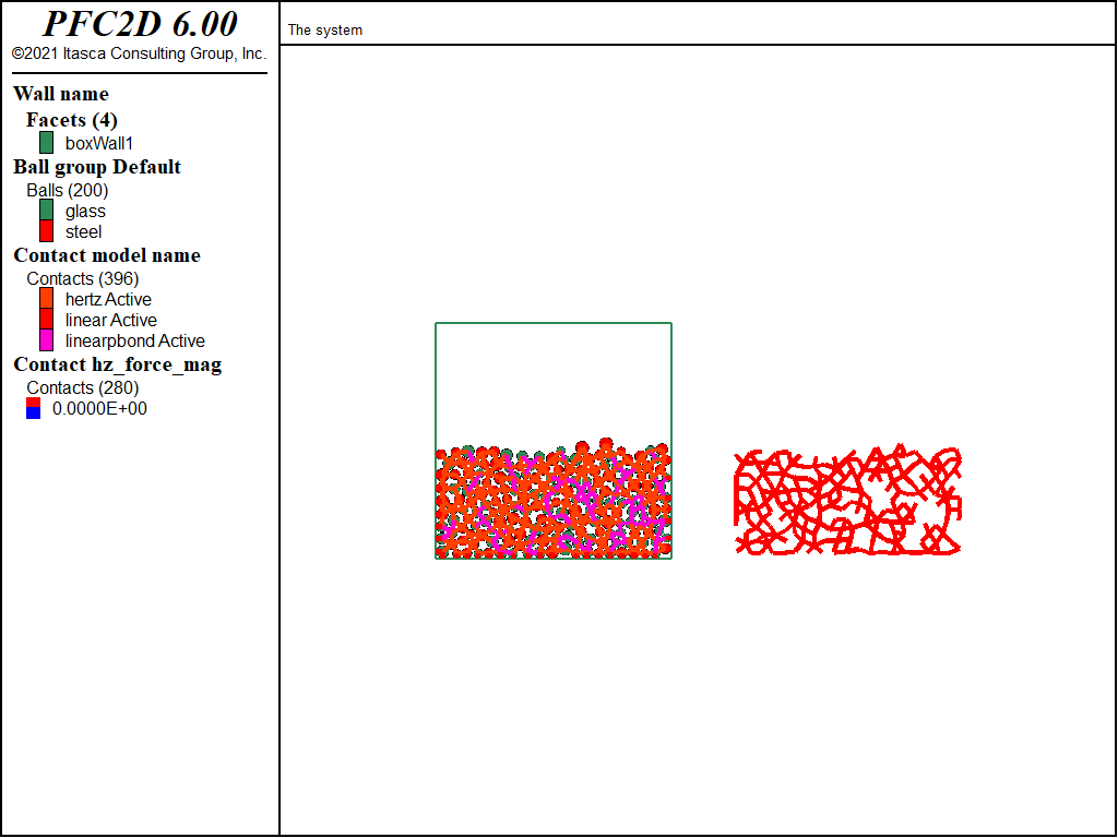
Figure 5: State of the system after issuing the contact cmat apply command to all contacts.
To modify glass-glass contacts while preserving the remaining contacts, a range can be specified along with the contact cmat apply command to restrict its action
to a select set of contacts (in this case, to contacts between glass balls).
; modify the 1st optional slot of the CMAT (contacts between glass balls)
contact cmat modify 1 model linearpbond                        ...
                    method deformability    emod 1e6 krat 0.5  ...
                           pb_deformability emod 1e6 krat 0.5  ...
                    property fric 0.25 dp_nratio 0.2           ...
                             pb_ten 1e8 pb_coh 1e8 pb_fa 30.0

; apply the CMAT to select contacts only. Note however that since the
; CMAT has been modified, further contacts created between glass balls will
; have the linear parallel-bond contact model installed.
contact cmat apply range group 'glass' matches 2
contact method bond
The state of the system after the commands above have been executed is shown in Figure 6. The left-hand side of the figure displays the contacts colored by the name of their contact model, and the right-hand side of the figure shows the hertz contacts colored by force. In this case, the linear parallel-bond contact model has been appropriately assigned to glass-glass contacts, and all the other contacts retained their previous contact model and data since only glass-glass contacts have been modified.
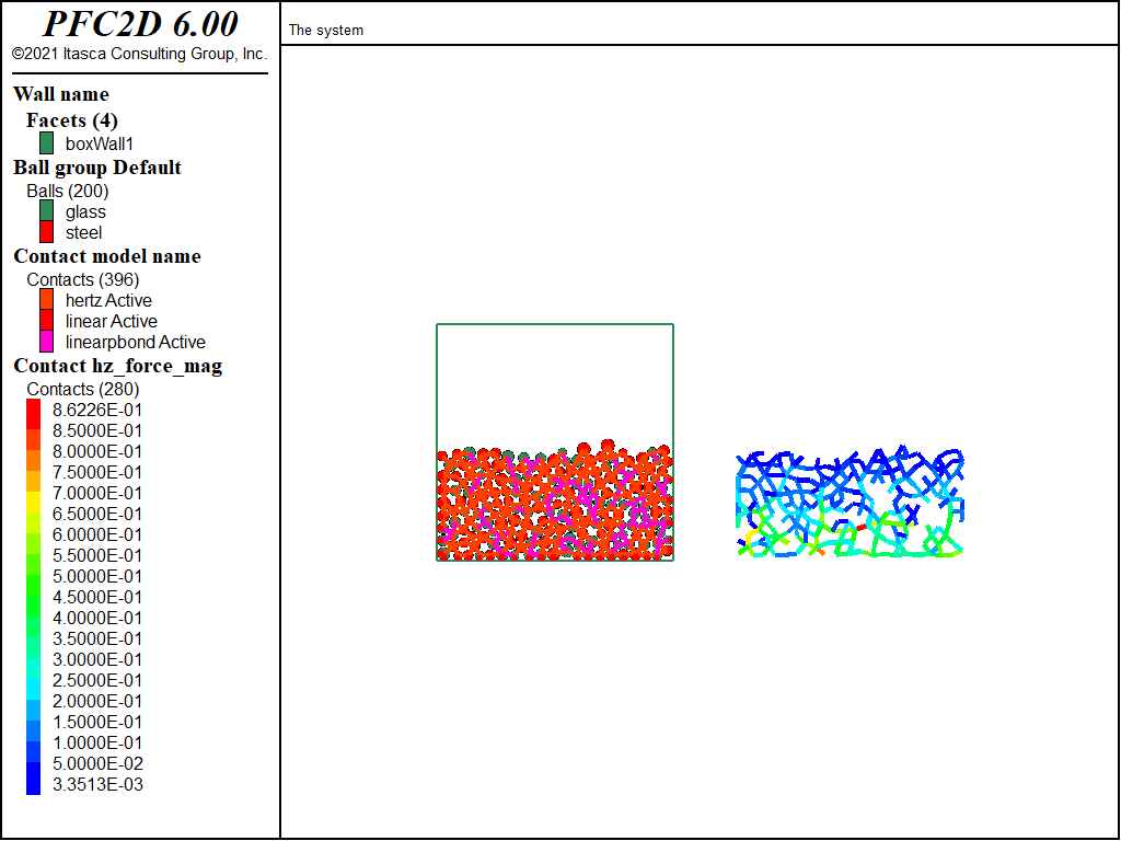
Figure 6: State of the system after issuing the contact cmat apply command to a select set
of contacts.
Although the strategy can be used to modify existing contacts, it is important to note that any changes to the CMAT will also impact future contacts created during further cycling. With the CMAT modified by the commands listed above, future contacts between glass balls will be assigned a linear parallel-bond contact model, which may not be desirable. One possibility to overcome this issue would be to revert the modifications in the CMAT, after the contact cmat apply command has been executed
to modify select contacts, in order to install a hertz contact model at new contacts between glass balls [4].
If the intent is to modify select contacts (or select contact model properties) at one point during the construction of the PFC model, using contact commands (that will only affect existing contacts) may be more adequate than altering the CMAT (which may affect future contacts). In the present case, only active contacts between glass balls may be modified to use a linear parallel-bond contact model with desired properties, which is accomplished by using the following commands:
contact model linearpbond range group 'glass' matches 2 contact gap 0.0
contact method deformability emod 1e6 krat 0.5     ...
               pb_deformability emod 1e6 krat 0.5  ...
               bond                                ...
        range contact model 'linearpbond'

contact property fric 0.25 dp_nratio 0.2           ...
                 pb_ten 1e8 pb_coh 1e8 pb_fa 30.0  ...
        range group 'glass' matches 2
The final state of the system is shown in Figure 7. Active contacts between glass balls have been assigned a linear parallel-bond model, bonds have been installed, and the system brought to equilibrium under gravity. All contacts (active and inactive) are displayed and colored by the name of their contact model. In this system, inactive contacts and new contacts between glass balls will use the appropriate hertz contact model (as defined in the corresponding slot of the CMAT).
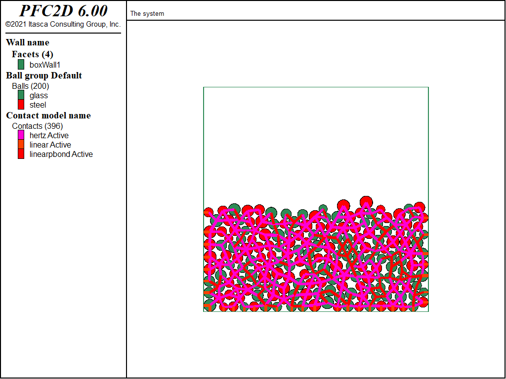
Figure 7: State of the system after installing the linear parallel-bond contact model at select contacts using contact commands.
Specifying the Proximity Distance
Another important feature of the CMAT is the ability to specify a proximity distance along with each slot of the CMAT. The proximity distance will be used to enforce a minimal distance at which contacts should be created during the course of the simulation (refer to “30.0 - Update Spatial Searching Data Structures” for further details). This can be useful, for instance, if modification of inactive contacts is desired, as illustrated below.
The data file “cmat6.p2dat” constructs a dense assembly of balls in a container (using a linear contact model for all contact types), then
uses the contact model command to install a linear parallel-bond contact model at ball-ball contacts and the contact property to modify properties
of those contacts.
At this stage, the contact method command is used to execute the bond method defined by the linear parallel-bond contact model.
By default, this method will install bonds at contacts with a gap less than or equal to zero, but a positive bond installation gap can also be specified.
Multiple cases are compared, with a bond installation gap of 0.0, 5 × 10⁻⁵, and 2.5 × 10⁻⁴. The corresponding systems are shown in
Figures 8 to 10, where the contacts colored by the value of the gap is shown on the left-hand side, and
the active and inactive linear parallel-bond contacts are displayed on the right-hand side. In this model, there are initially 1115 ball-ball contacts in total (active contacts with
a negative gap and inactive contacts with a positive gap), and the maximum gap for inactive ball-ball contacts is approximately 1.8343 × 10⁻⁴. Executing the bond method on contacts
with a gap less than or equal to zero (Figure 8) results in 983 contacts being bonded and 132 contacts remaining unbonded. Executing the bond method on contacts
with a gap less than or equal to 5 × 10⁻⁵ (Figure 9) results in 1025 contacts being bonded and 90 contacts remaining unbonded.
Finally, executing the bond method on contacts with a gap less than or equal to 2.5 × 10⁻⁴ (Figure 10) results in all 1115 ball-ball contacts being bonded.
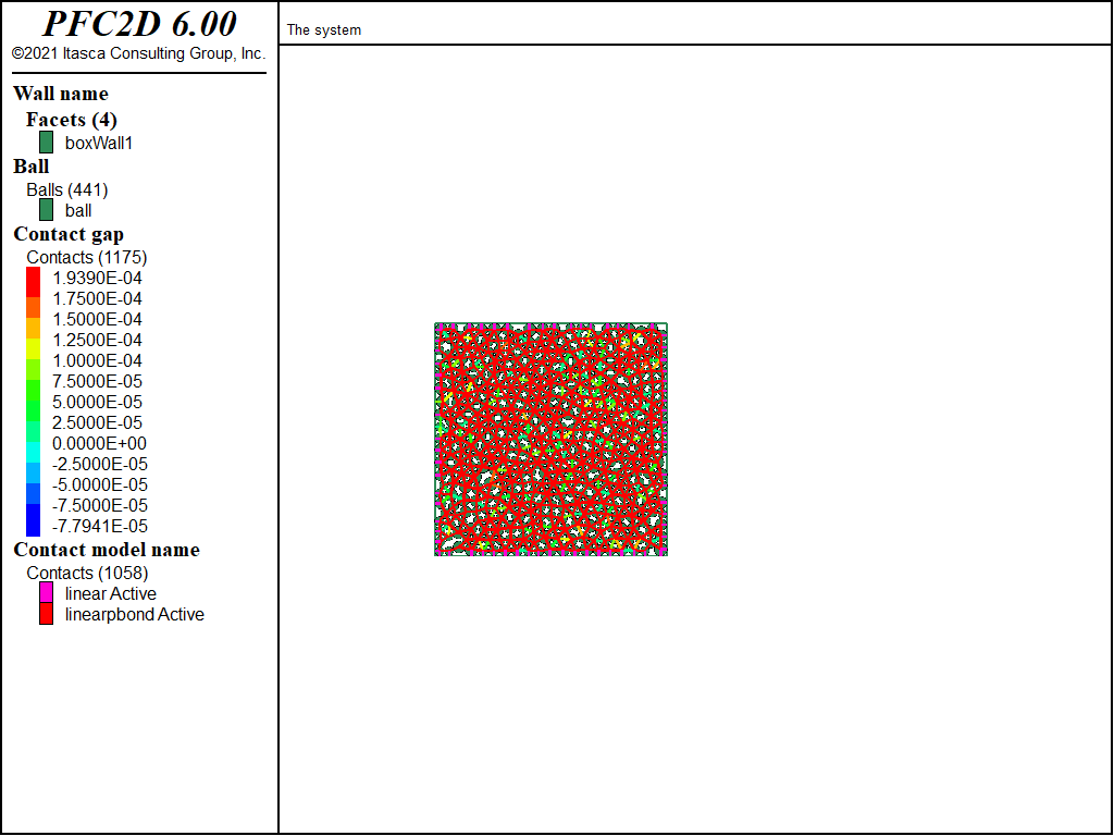
Figure 8: State of the system after bonding contacts (using the linear parallel-bond contact model) with a bond installation gap of 0.0.
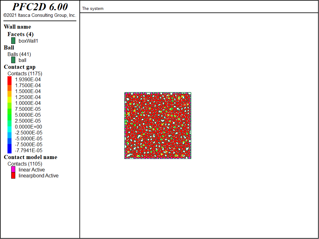
Figure 9: State of the system after bonding contacts (using the linear parallel-bond contact model) with a bond installation gap of 5 × 10⁻⁵.
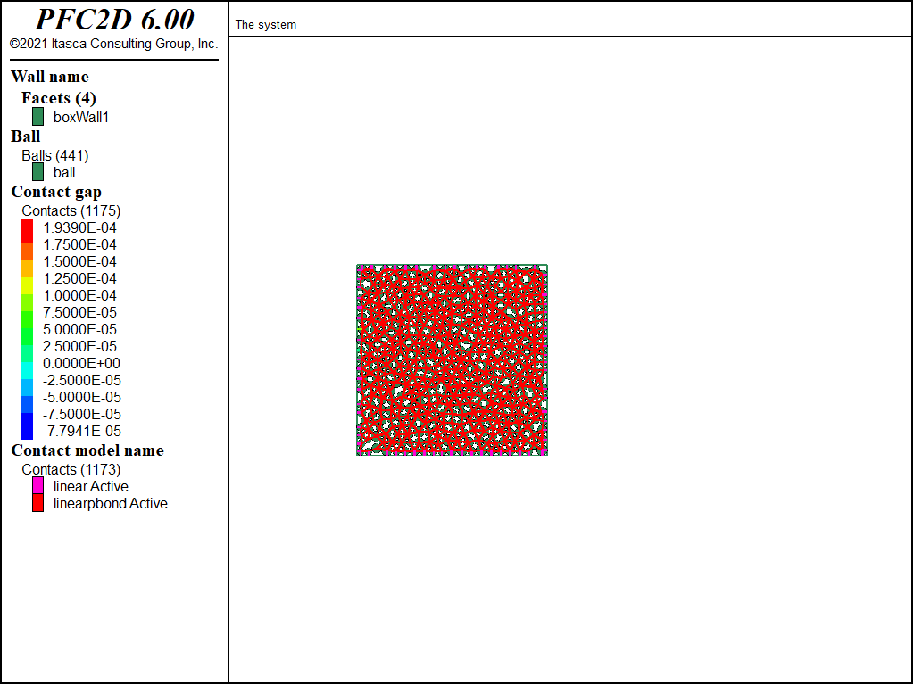
Figure 10: State of the system after bonding contacts (using the linear parallel-bond contact model) with a bond installation gap of 2.5 × 10⁻⁴.
Note, however, that since no proximity distance has been specified in the CMAT, the minimal distance at which inactive contacts have been created is left to the discretion of the contact detection logic.
In this case, this value (1.8343 × 10⁻⁴) is lower than the desired bond installation gap. Because the contact method command only operates on existing contacts, there may be pairs of
balls in the system with a gap between 1.8343 × 10⁻⁴ and 2.5 × 10⁻⁴, for which a contact has not been created, hence that are not bonded.
To ensure that a contact is created when balls come closer than a desired proximity distance, the CMAT may be modified to use the proximity keyword. For instance, the commands below
will modify the CMAT, model clean the model to force the creation of new contacts with the new proximity setting, apply the new CMAT entry to existing ball-ball contacts and, finally, bond the contacts with a
gap less than or equal to 2.5 × 10⁻⁴.
model restore 'cmat6'
contact cmat default type ball-ball   ...
                   model linearpbond  ...
                   property kn 1e6    ...
                   proximity 2.5e-4

; The CLEAN command forces contact detection
; Upon execution, new contacts are created, and we are sure that pairs with a
; separation distance <= 2.5e-4 now have an inactive contact
model clean
; The CMAT APPLY command must also be executed to modify existing contact
contact cmat apply range contact type 'ball-ball'

; the contacts with a gap <= 2.5e-4 can now be modified
contact model linearpbond range contact type 'ball-ball' gap 2.5e-4
contact property kn 1e6 ks 1e6 fric 0.5 ...
                 pb_kn 1e6 pb_ks 1e6    ...
                 pb_ten 1e8 pb_coh 1e8  ...
                 range contact model 'linearpbond'

contact method bond gap 2.5e-4
The final model is shown in Figure 11. With these new settings, there are 1280 contacts in total, with 1163 contacts being effectivley bonded. All the pairs of balls with a gap less than or equal to the desired value of 2.5 × 10⁻⁴ are bonded.
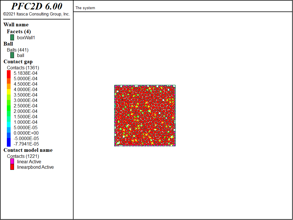
Figure 11: State of the system after bonding contacts (using the linear parallel-bond contact model) with a bond installation gap of 2.5 × 10⁻⁴.
Discussion
This tutorial illustrates the main uses of the CMAT and insists on important features that can be summarized as follows.
- The CMAT specifies which contact models should be installed when contacts are created. By default, PFC installs a null model contact model. The user is therefore required to set the CMAT.
- The CMAT comprises default slots attached to contact types and may also contain optional slots attached to ranges. Along with property inheritance, this provides flexibility to construct models with a heterogeneous distribution of contact constitutive behaviors.
- The CMAT may be modified and reapplied to all or select contacts. However, any changes to the CMAT may modify which contact models are installed at future contacts. To modify existing contacts only, the contact commands should be preferred.
- The minimal distance at which a contact may be created can be specified in the CMAT with the proximity keyword. This may be useful, for instance, to ensure that contacts are created within a desired distance and to be able to modify these contacts.
Endnotes
| [1] | These may be found in PFC2D under the “tutorials/using_cmat” folder in the Examples dialog ( on the menu). If this entry does not appear, please copy the application data to a new directory. (Use the menu commands . See the Copy Application Data section for details.) |
| [2] | In previous versions of PFC2D and PFC3D (up to version 4.0), the linear or Hertz contact models where assumed by default. There was no general mechanism available to easily use other contact models or several contact models in the same PFC model. Such models therefore used to require advanced and tedious FISH programming. The CMAT tool discussed herein is a general tool that allows to streamline such tasks. |
| [3] | The contact model properties are specific to each contact model. A list of built-in contact models is available here, and the description of each model contains a detailed listing of all its properties. |
| [4] | The range specified along with the contact cmat apply command should certainly also be refined to modify only active contacts. |
| Was this helpful? ... | PFC 6.0 © 2019, Itasca | Updated: Nov 19, 2021 |
