Liner-Reinforced Beam
Problem Statement
Note
To view this project in 3DEC, use the menu command . Choose “BlockSel/ Liner/ ReinforcedBeam” and select “ReinforcedBeam.prj” to load. The main data file used is shown at the end of this example. The remaining data files can be found in the project.
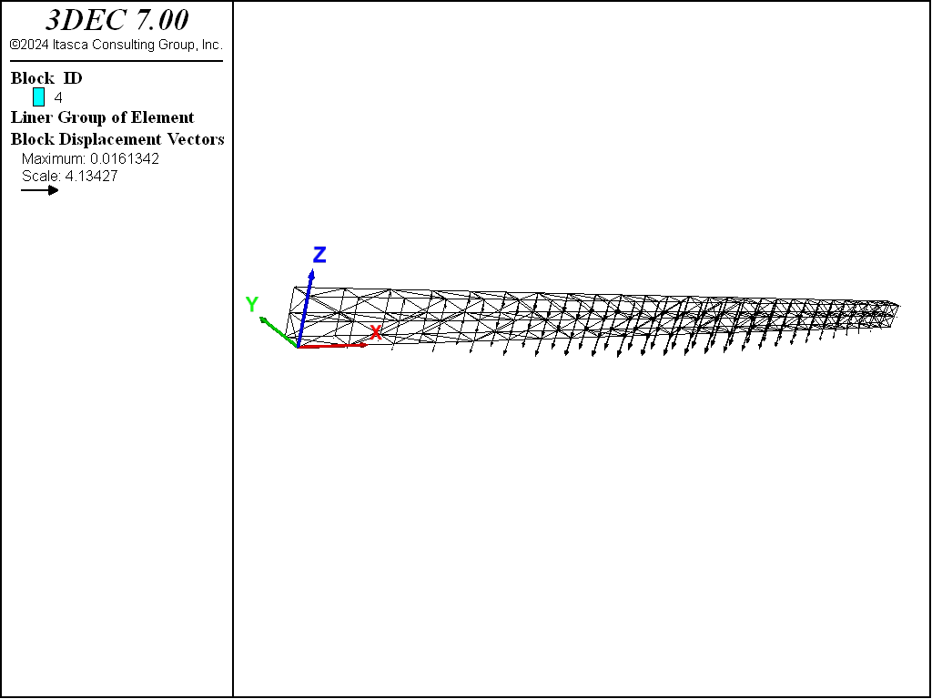
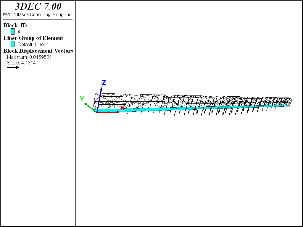
A simply supported wooden beam (\(E\) = 8.6 GPa, \(\nu\) = 0, length of 2.5 m, cross-section of 45 by 90 mm) has a concentrated load of 2000 N applied at its center. The beam is modeled with 312 3DEC zones. (Note that more zones are required to obtain the correct beam-theory solution. The system, as modeled, is too stiff; however, it is sufficient for the present example.) The 3DEC model and the displacement field are shown in Figure 1.
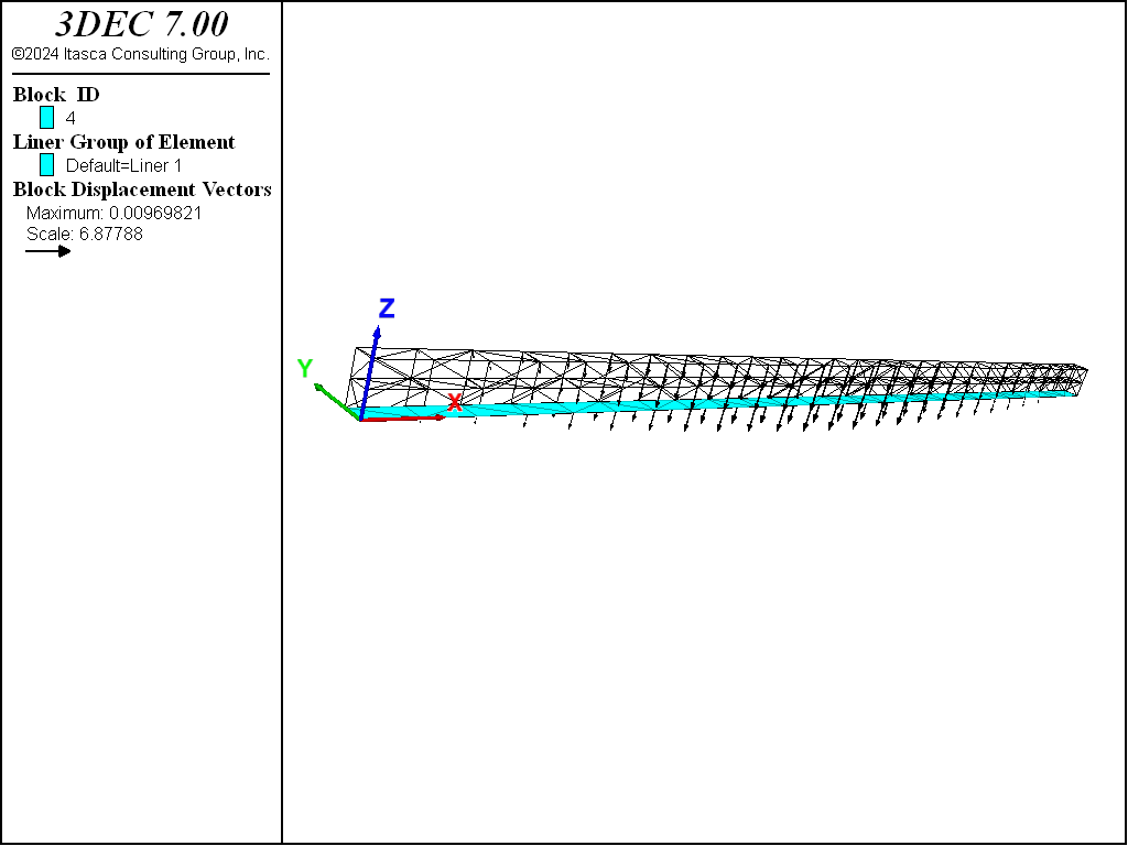
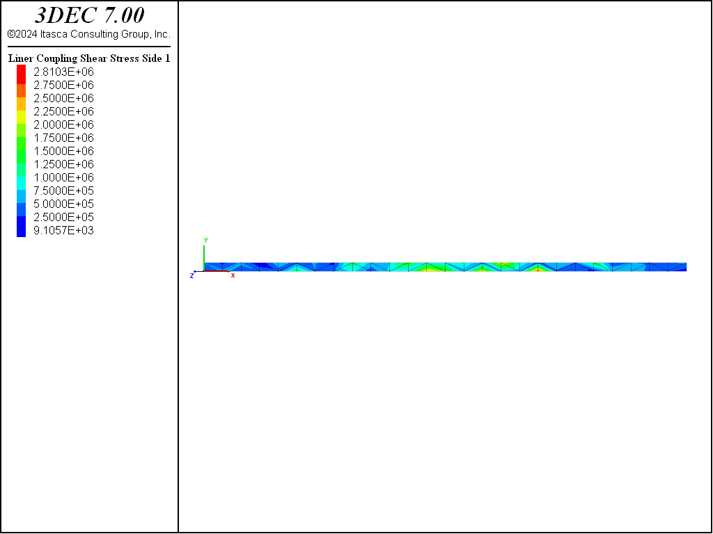
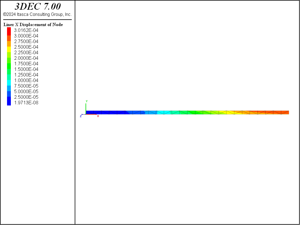
The problem is rerun with a 10 mm thick steel liner (\(E\) = 200 GPa, \(\nu\) = 0.3) attached to the beam bottom. By setting the liner cohesive strength to a large value, no slip is allowed to occur at the liner-beam interface. (The liner stiffnesses are chosen using the liner stiffness equation.) The displacement field of the liner-reinforced beam is shown in Figure 2. The presence of the liner has reduced the maximum mid-span deflection from 9.4 to 5.4 mm. Shear stresses have developed along the liner-beam interface (see Figure 3), and the maximum tensile \(xx\)-stress at the outer fiber of the liner is approximately 35 MPa (see Figure 4). The maximum tensile \(xx\)-stress at the liner mid-surface is 35 MPa. By setting the liner cohesive strength to zero, slip is allowed to occur along the liner-beam interface. The interface shear stresses go to zero, and the displacement field increases to almost match that of the unlined beam (see Figure 5). The liner continues to provide some stiffness to the composite system.
Data File
ReinforcedBeam.dat
; SEL Liner example application - Liner Reinforced Beam
model new
model random 10000
model large-strain off
model title 'Bending of a liner'
; Create zone geometry
block create brick 0 2.5 0 45e-3 0 90e-3
; make a cut for applying line load
block cut joint-set dip 90 dip-direction 90 or 1.25 0 0
; make cut to force two layers of zones across beam
block cut joint-set or 0 0 45e-3
block join
block zone generate edgelength 0.1

; Constitutive model and properties
block zone cmodel assign elastic
block zone property dens 2000 young 8.6e9 poisson 0
; Boundary Conditions
block gridpoint apply velocity-x 0 range position-x 0 position-z 0
block gridpoint apply velocity-z 0 range position-x 0 position-z 0
block gridpoint apply velocity-z 0 range position-x 2.5 position-z 0
block gridpoint apply force-z -1000 range position-x=1.25 position-z=90e-3

block face group 'Bottom' range pos-z 0
model save 'Start'

; --- Unlined case
model solve

model save 'Unlined'

; Lined Case
model restore 'Start'
; Create liner and properties
struct liner create by-block-face range group 'Bottom'
struct liner property isotropic=(200e9, 0.3) thickness=10e-3  ; steel
struct liner property coupling-stiffness-normal=1.9e12 ...
                      coupling-stiffness-shear=1.9e12  ...
                      coupling-cohesion-shear=1e20     ...
                      coupling-yield-normal=1e20
struct mechanical damping combined-local
model solve
model save 'Lined-NoSlip'

; Reduce liner shear strength
struct liner property coupling-cohesion-shear=0.0
model solve
model save 'Lined-Slip'
| Was this helpful? ... | PFC © 2021, Itasca | Updated: Feb 25, 2024 |

