Stability of an Open Pit in a Jointed Rock Mass
Problem Statement
Note
To view this project in 3DEC, use the menu command . Choose “3DEC/ ExampleApplications/ Open_Pit” and select “pit.prj” to load. The main data files used are shown at the end of this example. All data files are found in the project.
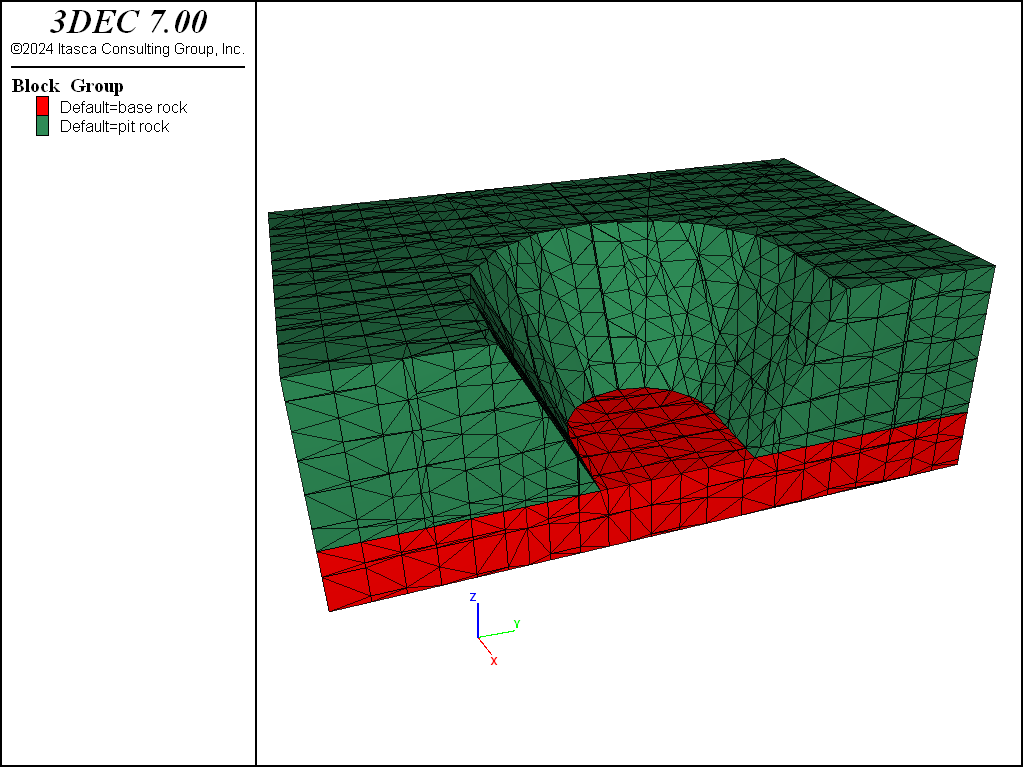
An open pit is to be excavated in a jointed rock mass. It is important to determine how the jointing will affect the stability of the pit walls. Of particular concern is the stability of the curved section of the pit, since joint orientations favor the creation of sliding wedges at that location. The model shown in Figure 1 represents a half-section of the open pit. The height of the slope is 25 m, and the slope angle is 63° (approximately 2 vertical to 1 horizontal). There are two joint sets with the following properties:
| Set 1 | Set 2 | |
| mean/sdev | mean/sdev | |
| dip (°) | 90/0 | 50/0 |
| dip direction (°) | 0/0 | 90/0 |
| spacing (m) | 5/1 | 4/1 |
| friction angle \(\phi\) (°) | 20 | 20 |
Modeling Procedure
The model shown in Figure 1 is generated with the file “PIT.DAT”. Before the pit is created, the two joint sets are cut. The FISH file “PITCR.FIS” is then called to create the half-section of the bathtub-shaped pit. The following parameters are specified for creation of the pit: elevation of the pit bottom (fyb); height of the slope (fht); coordinates of the center of curvature (fxc,zcyb); radius of the pit bottom (fr); number of segments to divide the curved section into (fn�_seg); and the slope angle (fslope�_ang).
For comparative purposes, the model is run with both rigid blocks and deformable blocks. The file “PITR.DAT” restores the model that was created with “PIT.DAT” just prior to zoning, to run the rigid block model. Considering that the dominant failure mode is expected to be sliding of individual blocks, either model should be able to predict whether the slope will be stable. For the deformable case, all of the blocks are zoned. Since stresses near the pit surface are low compared to the strength of the intact rock, the rock is assumed to behave as a linear elastic material.
Roller boundaries are placed around the sides of the model, and the bottom of the model is pinned. In the deformable-block case, this is done by using the block gridpoint apply command to specify zero velocity boundary conditions in the appropriate directions. In the rigid block model, roller boundaries must be simulated by placing fixed blocks around the model. This allows the user to avoid having to fix large blocks at the boundary of the model. The interface between the sides of the model and the surrounding blocks is made frictionless, and the interface with the bottom is given a high strength, to simulate pinning.
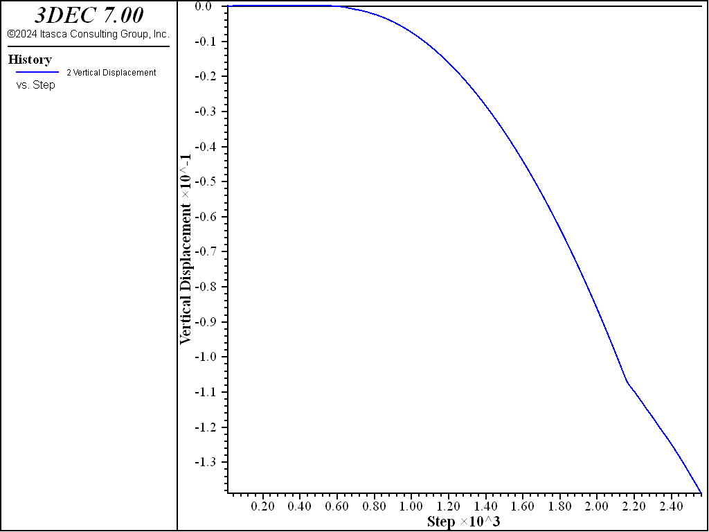
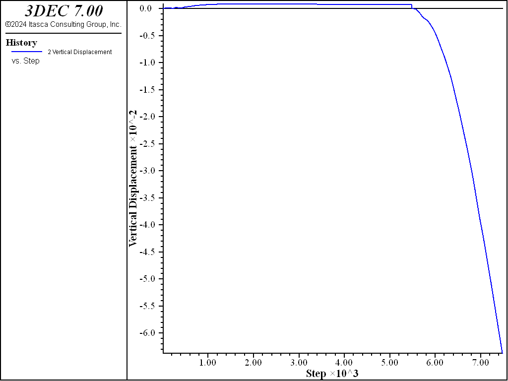
The model is first brought to an equilibrium state at high values for joint cohesion. The joint cohesion is then reduced to zero, and the model is run for 2000 steps. Displacement histories located at the pit crest are used to monitor the model response.
The deformable block model contains 964 blocks and 37,820 zones, and requires 32 MB of RAM.
Results
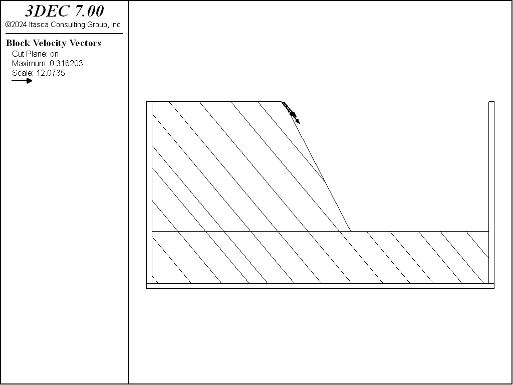
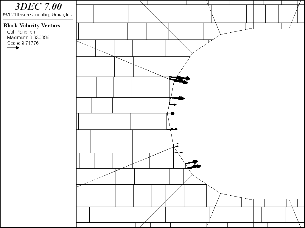
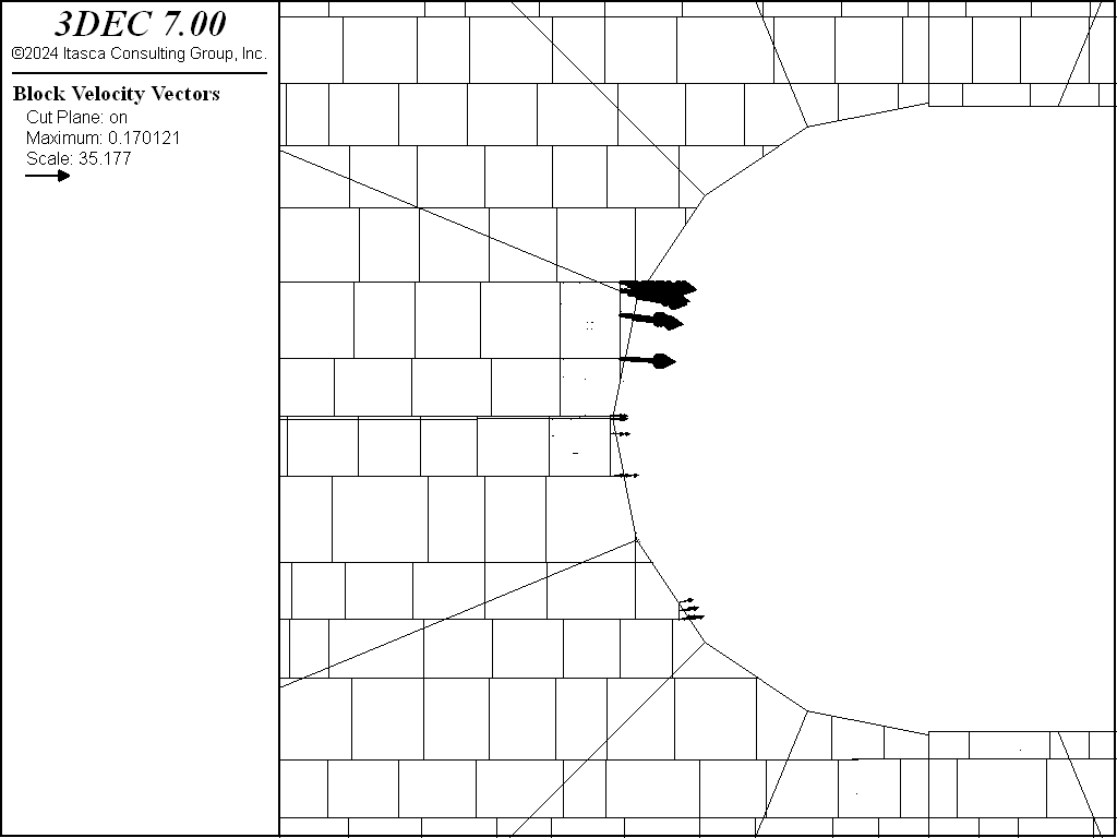
Plots of velocity on a vertical cross-section through the center of the pit are shown in Figures 2 and 3 for the cases of rigid and deformable blocks. Figures 4 and 5 are plots of velocity on a plan section just below the top of the model. Sliding of several blocks from the center of the curved section of the pit is predicted. In both cases, the width of the section predicted to fail is approximately 25 m. History plots of the vertical displacement of the pit crest at the end of the pit for the two cases are shown in Figures 6 and 7. The displacements do not level out, indicating that the sliding blocks are not stabilizing.
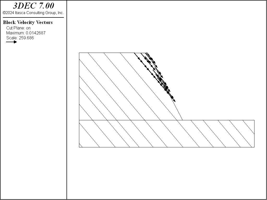
Figure 3: 3DEC plot of velocity vectors on a vertical cross-section through the pit — deformable blocks.
Data Files
pit.dat
model new
model random 10000
model large-strain on

block tolerance 1e-2

block create brick 75 140 50 150 -10 25
block group 'base rock'

;create joint sets
block cut joint-set dip 90 dip-direction  0 ori 100 100 0 spac 5 1 num 80
block cut joint-set dip 50 dip-direction 90 ori 100 100 0 spac 4 1 num 80

;create pit
program call 'pitcr.fis'

model save 'pit-geometry'

=======================================
;
; deformable block model
;zone model
block zone generate edgelength 4
;
;assign linear elastic block properties and joint properties
block zone cmodel assign elastic
block zone property bulk 2e8 shear 1e8 density 2800
block contact jmodel assign mohr
block contact property stiffness-normal 1e9 stiffness-shear 1e9 ...
                       cohesion 1e20 friction 20
block contact material-table default property stiffness-normal 1e9 ...
                                              stiffness-shear 1e9 friction 20

;boundary conditions
block gridpoint apply velocity-x 0.0 velocity-y 0.0 velocity-z 0.0 ...
                      range position-z -10
block gridpoint apply velocity-x 0.0 range position-x 75
block gridpoint apply velocity-x 0.0 range position-x 140
block gridpoint apply velocity-y 0.0 range position-y 50
block gridpoint apply velocity-y 0.0 range position-y 150

;initialize gravity stresses
model gravity 0 0 -10
block insitu stress -6.25e5 -6.25e5 -6.25e5 0 0 0 ...
             gradient-z 2.5e4 2.5e4 2.5e4 0 0 0

;histories
model history mechanical unbalanced-maximum
block history displacement-z position 101 97.5 25
history name '2' label 'Vertical Displacement'
;
;equilibrate
model solve
model save 'pit_eq'
;
;reduce strength
block contact property cohesion 0
block gridpoint initialize displacement 0 0 0
model cycle 2000
model save 'pit_fl'
;

program return
pitr.dat
model restore 'pit-geometry'
block group 'pit'
;
; rigid block model

;boundary conditions
block hide
block create brick  74 141  49  50 -10 25
block create brick  74 141 150 151 -10 25
block create brick  74  75  50 150 -10 25
block create brick 140 141  50 150 -10 25

block group 'sides'
block hide
block create brick 74 141 49 151 -11 -10

block group 'bottom'
block hide off range group 'sides'
block fix
block hide off

;initialize gravity stresses and create subcontacts
model gravity 0 0 -10
block insitu stress -6.25e5 -6.25e5 -6.25e5 0 0 0 ...
             gradient-z 2.5e4 2.5e4 2.5e4 0 0 0

;assign block properties and joint properties
block property density 2800

block contact jmodel assign mohr
block contact property stiffness-normal 1e9 stiffness-shear 1e9 ...
                       cohesion 1e20 friction 20
block contact material-table default property stiffness-normal 1e9 ...
                                              stiffness-shear 1e9 friction 20
block contact property cohesion 0 friction 0 ...
                       range group-intersection 'pit' 'sides'
block contact property cohesion 1e20 ...
                       range group-intersection 'pit' 'bottom'
;
;histories
model history mechanical unbalanced-maximum
block history displacement-z position 101 95 25
history name '2' label 'Vertical Displacement'

;equilibrate
model solve
model save 'pitr_eq'

;reduce strength
block hide range group 'bottom'
block contact property cohesion 0 tension 0
block hide off
block gridpoint initialize displacement 0 0 0
model cycle 2000
;
model save 'pitr_fl'

program return
pitcr.fis
; set geometric parameters for pit
fish auto-create off
fish define parm
  global zb=0
  global ht=25
  global xc=125
  global yc=100
  global r=12
  global n_seg=8.0
  global slope_ang=63
  global start_az=180
end
[parm]

; create pit
fish define create_pit
  command
    block cut joint-set dip 0 dip-direction 0 origin 0 0 [zb]
    block hide range plane dip 0 dip-direction 0 origin 0 0 [zb] below
    block group 'pit rock'
  end_command
  local ang_seg=180/n_seg
  global xp1=xc+r*math.sin(start_az*math.degrad)
  global yp1=yc+r*math.cos(start_az*math.degrad)
  global dd_seg=start_az+180+ang_seg/2
  loop local i (1,n_seg)
    local ang=start_az+ang_seg*(i)
    global xp2=xc+r*math.sin(ang*math.degrad)
    global yp2=yc+r*math.cos(ang*math.degrad)
    global dd_seg=start_az+180+ang_seg/2+ang_seg*(i-1)
    global dd_p1r=start_az+90+ang_seg*(i-1)
    global dd_p2r=start_az+90+ang_seg*(i)
    command
      block cut joint-set dip 90 dip-direction [dd_p1r] ...
                          origin [xp1] [yp1] 0 join
      block hide range plane dip 90 dip-direction [dd_p1r] ...
                          origin [xp1] [yp1] 0 below
      block cut joint-set dip 90 dip-direction [dd_p2r] ...
                          origin [xp2] [yp2] 0 join
      block hide range plane dip 90 dip-direction [dd_p2r] ...
                          origin [xp2] [yp2] 0 above
      block cut joint-set dip [slope_ang] dip-direction [dd_seg] ...
                          origin [xp1] [yp1] [zb] join
      block hide range plane dip [slope_ang] dip-direction [dd_seg] ...
                          origin [xp1] [yp1] [zb] below
      block group 'pit excavation'
      block hide
      block hide off range group 'pit rock'
    end_command
    xp1=xp2
    yp1=yp2
  end_loop
  global yu=yc+r
  global yl=yc-r

  command
    block cut joint-set dip 90 dip-direction 90 origin [xc] 0 0 join
    block hide range plane dip 90 dip-direction 90 origin [xc] 0 0 below
    block cut joint-set dip [slope_ang] dip-direction 180 ...
                           origin 0 [yu] [zb] join
    block hide range plane dip [slope_ang] dip-direction 180 ...
                           origin 0 [yu] [zb] below
    block cut joint-set dip [slope_ang] dip-direction 0 ...
                           origin 0 [yl] [zb] join
    block hide range plane dip [slope_ang] dip-direction 0 ...
                           origin 0 [yl] [zb] below
    block group 'pit excavation'
    block hide off
    block delete range group 'pit excavation'
  end_command
end
[create_pit]
⇐ Rough Square Footing on a Cohesive Frictionless Material | Assessment of Fault Slip Potential from Sill Pillar Mining ⇒
| Was this helpful? ... | PFC © 2021, Itasca | Updated: Feb 25, 2024 |

