
NorSand Model*
Note
*This model is available in FLAC3D only.
NorSand (Jefferies 1993, Jefferies and Been 2015) is a critical state model applicable to soils in which particle to particle interactions are controlled by contact forces and slips rather than bonds, intrinsically incorporating the state parameter so that it captures the behavior of granular soils over a wide range of confining stresses and densities. NorSand requires relatively few soil properties which are familiar and can be estimated from the routine laboratory or in-situ tests. NorSand explicitly captures the full range of soil behavior from static liquefaction of very loose soils through to dilation of very dense soils.
Formulations
Elastic Law
In the implementation of the NorSand model, the elasticity assumes the elastic shear modulus is
where \(p\) is the current mean pressure, and \(G_{ref}\), are material constants. A valid range for \(m\) is \(0 \le m \le 1\). \(p_{ref}\) is a reference pressure (usually, and by default, 100 kPa).
For \(m = 0\), \(G=G_{ref}\), which corresponds to a constant elastic shear modulus. For \(m = 1\), \(G = (G_{ref}/p_{ref})p = I_r p\), which corresponds to an elastic shear modulus being linear to the current \(p\) with a constant shear rigidity \(I_r=G_{ref}/p_{ref}\).
The corresponding elastic bulk modulus is
Critical State
The critical state requires \(D^p=0\) and \(\dot{D}^p/\dot{e}_q^p=0\), where the dilatancy \(D^p\) is defined as \(D^p=(\dot{e}_v^p)/(\dot{e}_q^p )\) with \(\dot{e}_v^p\) and \(\dot{e}_q^p\) are the rate of the plastic volumetric and deviatoric strain, respectively. If only \(D^p=0\) then this is an image state (denoted by the subscript \(i\)), variously also referred to as the pseudo steady state or phase change condition.
The critical state void ratio, \(e_c\) , can be a two-parameter semi-logarithmic form as
where \(\Gamma\) and \(\lambda\) are material constants.
The critical state void ratio, \(e_c\) , can be alternatively a three-parameter power-law form as
where \(C_1\), \(C_2\) and \(C_3\) are material constants.
State Parameter
The state parameter is defined as the difference of the current void ratio and the void ratio at the critical state:
The state parameter when \(p=p_i\) ( \(p_i\) is called the image stress) is defined as \(\psi_i\) by
Yield Surface
The outer yield surface of the NorSand model has the familiar bullet-like shape (Figure 1) of the original Cam-Clay model, which is expressed by
where \(p_i\) is called the image stress, which controls the size of the yield surface. \(\eta = q/p\) with \(q = \sqrt{3J_2}\), and \(J_2\) is the second invariant of the deviatoric stress tensor.
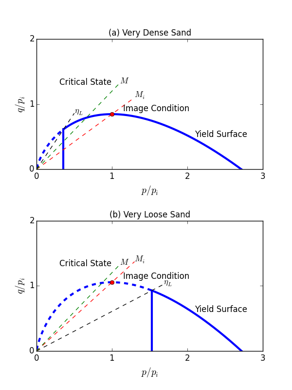
Figure 1: Schematic of NorSand yield surfaces and limiting stress ratios.
There is an internal cap so that the soil cannot unload to very low mean stress without yielding. This internal cap is taken as a flat plane, crossing the outer yield surface by the limiting stress ratio \(\eta_L\), and its location depends on the soil’s current parameters. Figure 1 illustrates the NorSand yield surfaces for two cases: very dense and very loose.
\(M_i\) is defined as
where
where \(M_{tc}\) is a material constant representing \(\eta\) at the critical state in the TC (triaxial compression) condition, \(N\) is Nova’s (1982) volumetric coupling coefficient, and \(g(\theta)\) is a function considering the effect of the Lode’s angle \(\theta\), defined by
to interpolate \(M_{\theta}=g(\theta,c) M_C\) for a given Lode angle \(\theta\) and the strength ratio \(c\), which is defined by \(c = M_{te}/M_{tc} = 3/(3+M_{tc})\), with \(M_{te}\) the triaxial compression strength, \(M_{tc}\) the triaxial extension strength.
It is easy to verify that
so
According to Jefferies and Been (2015), \(\chi_i\) can be approximated by
where \(\chi_{tc}\) is a material constant.
Stress Dilatancy
By assuming the associated flow rule, the stress dilatancy can be expressed as
where \(\dot{e}_v^p\) and \(\dot{e}_q^p\) are the rate of the plastic volumetric and deviatoric strain, respectively.
The detailed expressions of the plastic strain rates in the principal stress space are somewhat tedious, which can be found in Jefferies and Shuttle (2005).
Hardening Rule of Outer Cap
The image stress \(p_i\) controls the size of the yield surface. The hardening rule in the implementation is defined by
where the hardening modulus \(H\) is expressed by
with \(H_0\) and \(H_y\) being material constants. The default value of \(H_y\) is zero so that \(H\) equals to the constant \(H_0\) for this case. The cut-off of \(H\) is 10 and \(0.5/(\lambda-\kappa)\), whichever is larger. For the case of three-parameter power-law form for critical state, \(\lambda\) is approximated to be the slope of the critical state curve at the initial \(p\).
\(p_{i,m}\) is defined as
The additional cap softening term \(T_S\) is optional (e.g., inputting \(S=0\) will nullify this term) and the current version of \(T_S\) is
\(S\) is 0 by default, and it is allowable to be \(0 \le S \le 1\) for undrained analysis. A larger \(S\) value will lead to faster softening of a loose sand during an undrained shearing loading. Please be aware that the additional term \(T_S\) is still in debate, it should be cautious to use \(S>0\). It is not recommended to use \(S>0\) for any case of drained loading.
The last term \(T_{PSR}\) in Eq. (14) is capturing the effects of principal stress rotation (Jefferies et al 2015):
where \(Z\) is a soil property and \(r=\exp{(1)} \approx 2.718\) is the yield surface spacing ratio (a fixed value), and \(\alpha\) is the current included angle between direction of major principal stress and z-coordinate frame of reference in 3D version. To capture the cyclic mobility in a dynamic simulation, \(Z\) should be input a positive value.
Hardening Rule of Inner Cap
The hardening rule for the inner cap in the implementation is defined by
where \(H_i\) is a material parameter with a default value 5.0. Yielding of the inner cap always drag the bullet-like outer surface smaller. NorSand uses one plausible idealization that involves imaging the stress \(q\) on the cap across the outer yield surface (Jefferies and Been 2015). By default (flag-inner = off), inner cap hardening is not activated. To activate this option, input the material property flag-inner to on.
Initial Conditions
The NorSand model is a stress-dependent model. The initial conditions include the initial stress, \(\sigma_{ij,0}\), initial state, \(e_0\) or \(\psi_0\), and over-consolidation ratio, OCR. OCR in this model (Figure 2) is defined as the ratio of the current \(p_i\) over the calculated \(p_{i, OCR=1}\) so that the initial stress is on the yield surface assuming OCR = 1.
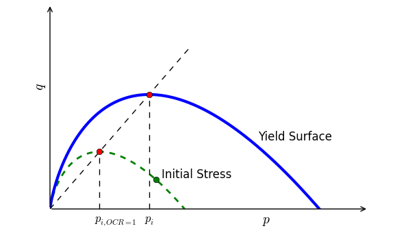
Figure 2: Schematic of OCR in the NorSand model.
Reasonable initial stress should be input the first time the NorSand model is assigned. The stress can be initialized through commands or a FISH function. A common procedure is to generate the initial stress by running the model using a simpler constitutive model (e.g., linear elastic or Mohr-Coulomb model), then change the constitutive model into NorSand but keep the calculated stress. The calculated stress from the other model can be used as the initial stress of the NorSand model. Details on implementation and verification can be found in Cheng and Jefferies (2020).
NorSand model is recommended for static analysis (e.g., static liquefaction).
Acknowledgment
The implementation of this model was partially sponsored by VALE S. A. and Inst. Tecnológico Vale.
References
Cheng, Z. and M. Jefferies. Implementation and verification of NorSand model in general 3D framework. in Geo-Congress: Geotechnical Earthquake Engineering and Special Topics, ASCE, 10-19 (2020).
Jefferies, M.G. Nor-Sand: a simle critical state model for sand. Géotechnique, 43(1), 91-103 (1993).
Jefferies, M., and K. Been. Soil liquefaction: a critical state approach. CRC press (2015).
Jefferies, M.G., and D.A. Shuttle. NorSand: Features, calibration and use. in Soil Constitutive Models: Evaluation, Selection, and Calibration, 204-236 (2005).
Jefferies, M., D. Shuttle, and K. Been. Principal stress rotation as cause of cyclic mobility. Geotechnical Research, 2(2), 66-96 (2015).
norsand Model Properties
Use the following keywords with the zone property command to set these properties of the NorSand model.
- norsand
- critical-state-1 f
- critical-state-2 f
- critical-state-3 f
critical state parameters, \(C_1\), \(C_2\) and \(C_3\). Parameters to determine the critical state line. If \(C_3=0\) (by default), the critical state is based on the 2-parameter equation, assuming \(C_1=\Gamma\) and \(C_2=\gamma\); If \(C_3>0\), the critical state is based on the 3-parameter equation.
- factor-coupling f
volumetric coupling factor, \(N\). The default value is 0.3.
- factor-dilatancy f
parameter relating minimum dilatancy to the corresponding \(\psi\) at the TC condition, \(\chi_{tc}\). The default value is 4.0.
- hardening-0 f
plastic hardening modulus when \(\psi=0\), \(H_0\).
- modulus-annealing f
plastic softening modulus for PSR, \(Z\). The default value is 0, which will not consider PSR effect.
- shear-reference f
reference shear modulus, \(G_{ref}\).
- ratio-critical f
stress ratio at the critical state at the TC condition, \(M_{tc}\). The default value is 1.2, which corresponds to a critical friction angle of 30 degrees.
- exponent f (a)
exponent of pressure dependence defining elasticity, \(m\). The default value is 1.0.
- hardening-inner f (a)
plastic hardening modulus value for the hardening of inner cap, \(H_i\). This value is meaningful only when flag-inner = :lbool:`on`. The default value is 5.0.
- modulus-annealing f (a)
plastic softening modulus for PSR, \(Z\). The default value is 0, which will not consider the PSR effect.
- over-consolidation-ratio f (a)
over consolidation ratio, \(OCR\). The default is 1.
- hardening-y f (a)
another hardening modulus parameter, \(H_y\), so that the real plastic hardening modulus is following \(H=H_0-H_y\psi\). The default value is zero.
- pressure-reference f (a)
reference pressure (usually the standard atmospheric pressure), \(p_{atm}\). The default value is 100.0 if in kPa. This parameter should always be referred to the standard atmospheric pressure and it does not need extra calibration. Its value should be input in a unit of stress/pressure consistent with the other parameters used in the simulation.
- poisson f (a)
Poisson’s ratio, \(\nu\). The default value is 0.2.
- stress-xx-initial f (i)
initial xx component of the effective stress, \(\sigma^0_{xx}\). This parameter will not be updating.
- stress-yy-initial f (i)
initial yy component of the effective stress, \(\sigma^0_{yy}\). This parameter will not be updating.
- stress-zz-initial f (i)
initial zz component of the effective stress, \(\sigma^0_{zz}\). This parameter will not be updating.
- stress-xy-initial f (i)
initial xy component of the effective stress, \(\sigma^0_{xy}\). This parameter will not be updating.
- stress-yz-initial f (i)
initial yz component of the effective stress, \(\sigma^0_{yz}\). This parameter will not be updating.
- stress-xz-initial f (i)
initial xz component of the effective stress, \(\sigma^0_{xz}\). This parameter will not be updating.
- state-parameter-initial f (i)
initial state parameter, \(\psi_0\). If \(e_0 \le 0\), the initial state will be represented by this initial state parameter, and \(e_0\) will be calculated by \(\psi_0\). This parameter will not be updating.
- void-initial f (i)
initial void ratio, \(e_0\). If \(e_0 \ge 0\), the initial state will be represented by this initial void ratio instead of initial state parameter, and \(\psi_0\) will be calculated by \(e_0\). This parameter will not be updating.
- angle-psr f (r)
Current included angle between direction of major principal stress and z-coordinate frame of reference, \(\alpha\).
- bulk f (r)
current elastic bulk modulus, \(K\).
- shear f (r)
current elastic shear modulus, \(G\).
- ratio-image f (r)
current stress ratio for image state at the TC condition, \(M_{i,tc}\).
- stress-image f (r)
current image stress, \(p_i\).
- stress-image-maximum f (r)
current allowable maximum image stress, \(p_{i,max}\).
- state-parameter f (r)
current state parameter, \(\psi\).
- state-parameter-image f (r)
current state parameter for image stress, \(\psi_i\).
- void f (r)
current void ratio, \(e\).
Key
- (a) Advanced property.
- This property has a default value; simpler applications of the model do not need to provide a value for it.
- (i) Initial property.
- This property will not be updated once initialized (first input).
- (r) Read-only property.
- This property cannot be set by the user. Instead, it can be listed, plotted, or accessed through FISH.
| Was this helpful? ... | PFC © 2021, Itasca | Updated: Feb 25, 2024 |