
Working With Geometric Data
When using geometric data, it is generally required to have it displayed as transparent. While it is possible to show the geometry as opaque, it will interfere with much of the interactive functionality. This applies even to geometric data that contains only lines and no polygons.
Point-to-Point Snapping
After you import a geometric data set (.DXF, .STL, or Itasca .GEOM file) you can use point-to-point movement to make blocks conform to features of the geometry.
For example, to snap a block to the corner of a geometric figure, you can:
- select the block,
- Shift+click a point on the block (call it Point A), and
- Shift+click the intersection of edges at the corner of the figure (call that Point B).
- The selected block moves the distance and direction specified by a Point A to Point B move.
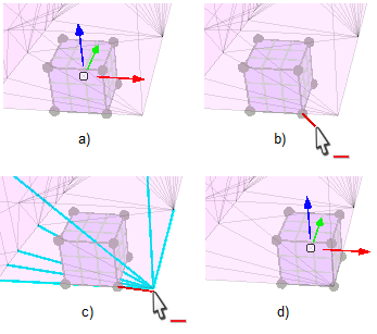
One or more selected faces can be moved using the same technique:
Any selected object(s) can be moved using point-to-point snapping.
There is a special case for point-to-point snapping: if nothing is selected when you Shift+click Point A, Point A will automatically get selected and, after the move, get deselected. This facilitates quicker snapping of a series of points to geometric features.
When you have a block inside a geometric shape and you want to pull points outward to meet a polygon, you can rotate the model so that when you pull the point toward you, it snaps to the location on the polygon directly between you and the point.
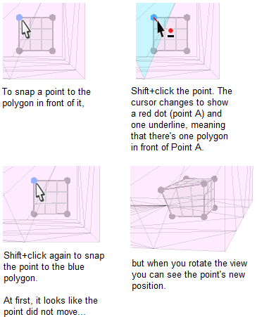
A body point or control point can be snapped to geometry in front of it but will not snap through building blocks to geometry behind a block.
When you Shift+click to set Point A, there are several cursor changes that help show what is happening. The first 4 cursors below show up only when the mouse is over Point A and the Shift key is down.
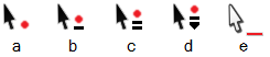
- Mouse cursors:
- Cursor ‘a’ shows that there are no polygons in front of Point A (the red dot).
- Cursor ‘b’ shows that there is one polygon in front of Point A.
- Cursor ‘c’ shows there are two polygons in front of Point A.
- Cursor ‘d’ shows there are more than 2 polygons in front of Point A.
- Cursor ‘e’ reminds you, even when the Shift key is not down, that a Point A is specified.
When more than one polygon is in front of Point A, you can use the mouse wheel to choose which polygon to snap to. The mouse wheel has the effect of peeling off layers of polygons, letting you snap to points, edges and polygons deeper inside the model. The mouse wheel won’t change the cursor shape but will change the polygon, point or edge that gets highlighted. An alternative to using the mouse wheel is to use the Shift key plus an up or down arrow key to move through geometry layers.
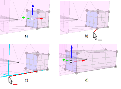
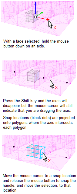
1D Snapping
The technique of 1D (one dimensional) snapping can be used with geometric data. 1D snapping will cause a selection to be moved only along a specified axis to a snappable location. Such locations include intersections of geometric edges, snap targets projected onto polygons, as well as body points.
An example of snapping to a polygon:
Draping
When you have a geometric data file showing a surface that you would like building blocks to conform to, you can use the drape command. This command will move body points and control points in the direction you specify until they meet a polygon in the geometric set. (The geometric set must have polygons, not just lines.) It’s best to add enough blocks and control points to obtain the amount of resolution you want before you use the drape command.
Example command:
building-block point drape direction (0,0,1) range position-z 240 250
The direction, specified along the x, y and z axes, determines the direction the points will move. The range, in this case coordinates along the z axis, determines which points will be moved.
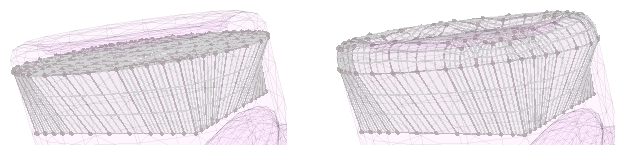
After using the drape command, you may examine the results and notice that some areas need more resolution. Resolution can be increased by splitting blocks or by adding control points to selected edges or faces and then using 2 more drape commands in opposite directions along the same axis. Be sure to use new range coordinates to specify which points to move.
- To add control points to a selected range of edges: click an edge to establish edges as the seed selection type, then drag the mouse over a range of edges to select them, then locate the “Edge Control Pts” line in the Object Properties control set. Change the “Edge Control Pts” value to set the number of control points to use for each selected edge.
- Similarly for faces, select some faces and use the “Face Ctrl Pts” line in the Object Properties control set. Face control points can be seen while the “Add control points” tool ( ) is selected.
Note: If you plan to use more than a few hundred control points in your model, you may want to add them as one of the last steps because the validation process slows down greatly as more control points are added. Validation occurs whenever a control point or the end point of an edge moves.
Using the Control Panel for Draping
Instead of using the command line, you can use the Drape controls in the Object Properties control set. In this case you would select an edge to indicate the direction to do draping in and click the button in the control set to copy the edge’s vector to the drape controls. Then select the points, edges or faces you want to move and click one of the draping buttons to move points in the direction of your choice.
Draping to Building Blocks
Building blocks don’t drape to building blocks, but you can copy building blocks to geometric data and drape to them that way. See this section for more details.
| Was this helpful? ... | PFC © 2021, Itasca | Updated: Feb 25, 2024 |