
Subsidence above Horizontal Cut
Problem Statement
Note
To view this project in FLAC3D, use the menu command . Choose “ExampleApplications/HorizontalCut” and select “HorizontalCut.prj” to load. The project’s main data file is shown at the end of this example.
The ground settlement (subsidence) profiles above the horizontal cut are compared for the models using the Mohr-Coulomb and Mohr-Coulomb Tension Crack (MohrT) models with the same material parameters (Table 1). The material cohesion is assumed to be very large to prevent any shear failure.
This is a plane-strain problem with the model dimensions of 100 m (length) × 60 m (depth). The 30 m wide and 1 m high horizontal cut is at the 15-15.5 m depth (floor depth). The fixed boundary is assumed at the base and sides of the model. The vertical stress is initialized to be compatible with the gravity field. The horizontal stress is initialized assuming the lateral stress coefficient of 0.75. An interface is set between the floor and the roof of the cut so that the cut can close without the roof and the floor overlapping. The material density is 1600 kg/m3, and the gravity is assumed to be 10 m/s2. The model mesh is shown in Figure 1.
| Material Parameter | Value |
|---|---|
| \(K\) (Pa) | 4e7 |
| \(G\) (Pa) | 3e7 |
| \(\phi\) | 0 |
| \(\psi\) | 0 |
| \(c\) (Pa) | 1e20 |
| \(\sigma^t\) (Pa) | 2000 |
The tension failure zones are plotted in Figure 2 and Figure 3 for Mohr-Coulomb and MohrT models, respectively. The vertical displacement contour profiles are plotted in Figure 4 and Figure 5 for Mohr-Coulomb and MohrT models, respectively. The settlement predicted by the MohrT model (Figure 6) is much greater than that predicted by the Mohr-Coulomb model (Figure 7) in this example.
The zones above the cut undergo initial extension in the vertical direction, which in this case results in tensile failure (corresponding to formation and opening of the horizontal fractures). Subsequently, as the cut closes and the roof contacts the floor, continuous deformation of the overburden will reverse the vertical strain in the immediate roof zones. This reversal of the strain should result in the closure of the open horizontal fractures. However, the irreversible tensile plastic strain in the Mohr-Coulomb model will prevent this crack closure. (See Single Zone Loading-Unloading Test with MohrT Model.)
The apparent material dilation (“ratcheting”) will result in generation of the vertical compressive stresses immediately after the vertical strain changes the sense. That back-pressure (caused by compressive stresses) to the overburden will reduce vertical deformation and subsidence. The MohrT model allows complete closure of the horizontal fractures and prevents artifice of the Mohr-Coulomb model that results in underestimation of subsidence in this example. In addition to the settlement profile, another major difference in the results of these two models is the shape of the failure zone above the roof.
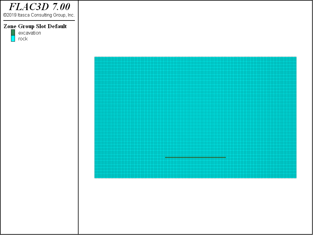
Figure 1: Model grid.
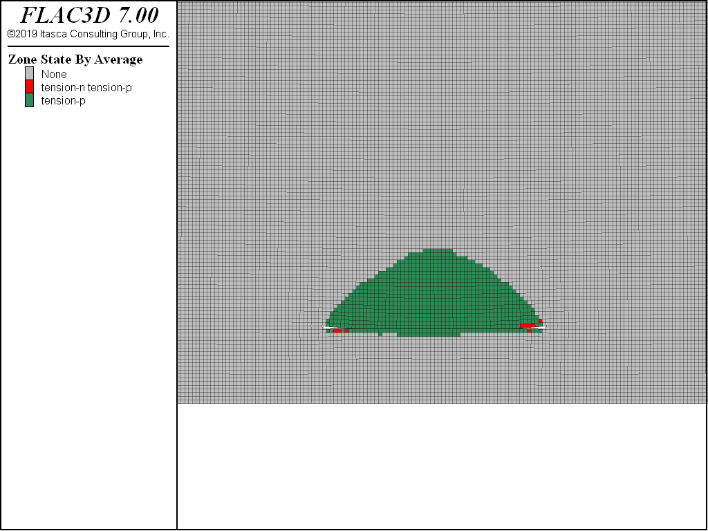
Figure 2: Tension failure zones using Mohr-Coulomb model.
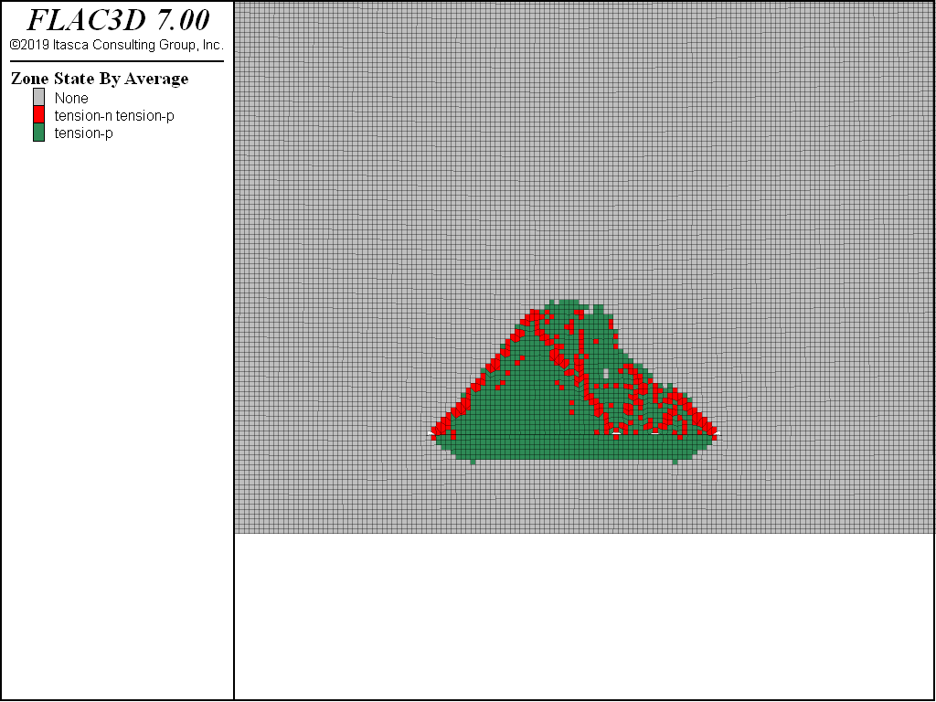
Figure 3: Tension failure zones using MohrT model.
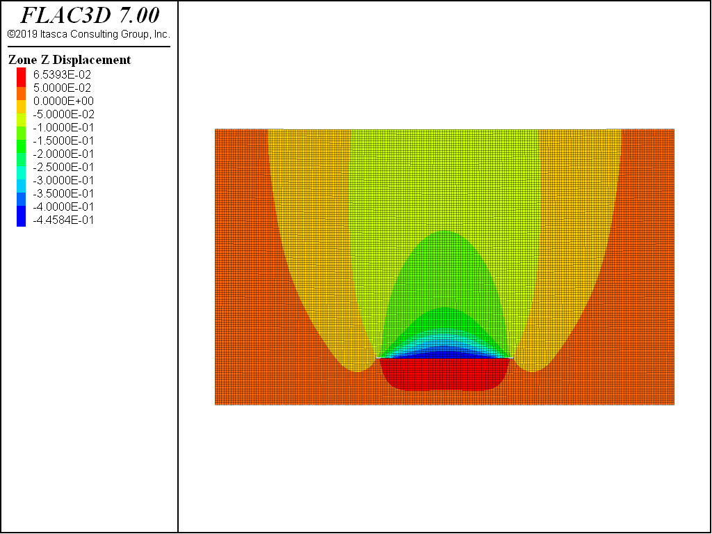
Figure 4: Vertical displacement contour using Mohr-Coulomb model.
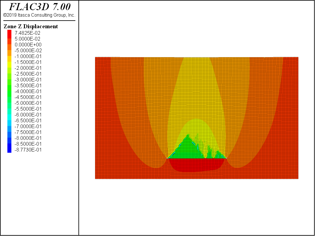
Figure 5: Vertical displacement contour using MohrT model.
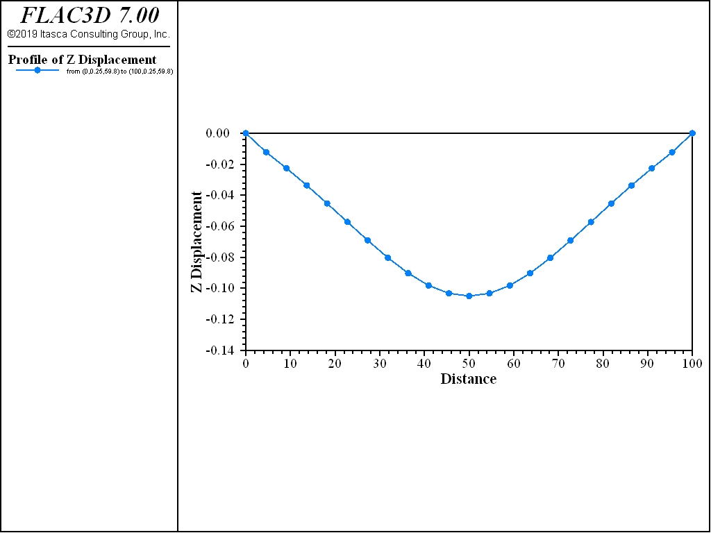
Figure 6: Vertical displacement contour using Mohr-Coulomb model.
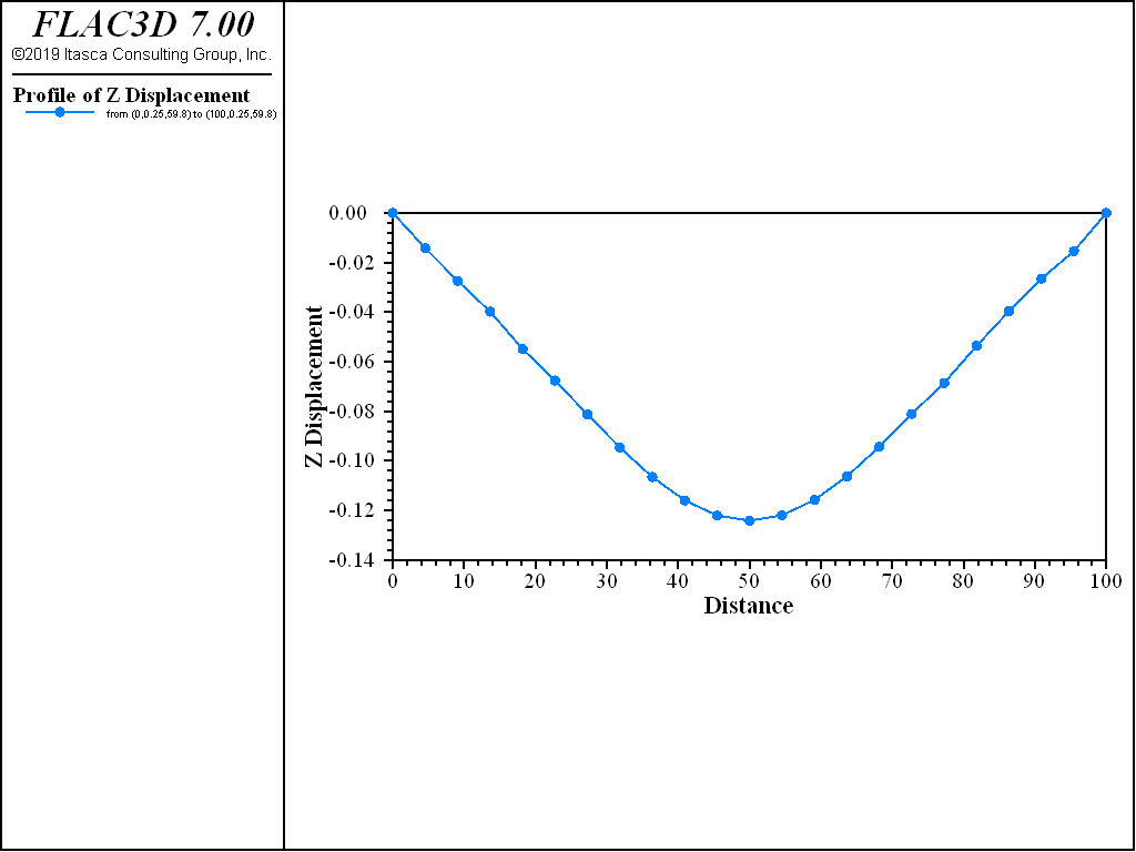
Figure 7: Vertical displacement contour using MohrT model.
Data File
HorizontalCut-MohrT.dat
model new
model large-strain off
model gravity 10
zone create brick size 200 1 120 point 0 (0,0,0) point 1 (100,0,0)  ...
                  point 2 (0,0.5,0) point 3 (0,0,60) group 'rock'
zone group 'excavation' range position-x 35. 65. position-z 10. 10.5
zone cmodel assign mohr-coulomb-tension
zone property density 1600. bulk  4e7  shear 3e7 cohesion 1e20 tension 2000
zone gridpoint fix velocity   range union position-x 0 position-x 100
zone gridpoint fix velocity-y
zone gridpoint fix velocity-z range position-z 0
zone initialize-stress ratio 0.75
model solve
zone gridpoint initialize displacement (0,0,0)
zone interface create by-face separate ...
                      range group 'excavation' group 'rock' position-z 10.5
zone interface node property stiffness-normal 4e8 stiffness-shear 4e8 ...
                             friction 30.
model large-strain on
;zone relax excavate range group 'excavation'
zone delete range group 'excavation'
model solve
model save 'mohrt'
| Was this helpful? ... | PFC © 2021, Itasca | Updated: Feb 25, 2024 |