Importing and Merging
Zones can also be created by importing from a file. There are two ways to do this: import from a grid file block import command, or import blocks as commands and “merge” them to create zones. These two methods are described in the following sub-sections.
Importing From a Grid File
A 3DEC grid file is an ASCII-format or binary-format file description of the block geometry (vertexes, faces (rigid block), zones (deformable blocks) and block groups). The binary-format file size will be smaller than the ASCII-format file size, and it takes less loading time if being imported. The ASCII-format grid file specification can be found with the block zone import command description. If no file extension is given, an extension of “3dgrid” is used.
With the command block import filename s, a file names s is imported. The command creates a new vertex for every point specified in the input file. A rigid block is defined by a collection of faces and a deformable block is defined by a collection of tetrahedral zones. The grid file may also hold group information for blocks and zones.
In addition, the grid file may hold information to assign joint-set IDs to specific contacts, and/or group names to contact. An example grid file (ASCII) and the resulting model is shown below.
An example grid file is shown below. This model defines 2 zoned blocks with a single joint. The resulting model is shown in Figure 1.
* 3DEC grid produced by 3DEC 7.00 Pre-Release 123
* Fri Jul 17 10:52:19 2020
TOL   3.60000000000000e-02
* GRIDPOINTS
G         1  -2.00000000000000e+01  -2.00000000000000e+01  -2.00000000000000e+01
G         2   1.00000000000000e+01  -2.00000000000000e+01  -2.00000000000000e+01
G         3   1.00000000000000e+01   1.00000000000000e+01  -2.00000000000000e+01
G         4  -2.00000000000000e+01   1.00000000000000e+01  -2.00000000000000e+01
G         5  -2.00000000000000e+01  -2.00000000000000e+01   1.00000000000000e+01
                        .
                                                .
                                                .

G       389  -1.19034744602300e+01  -1.60151236941150e+01  -8.75834604299203e+00
G       390  -1.60659304827419e+01  -1.64589286024737e+01  -5.21286966750346e+00
G       391  -5.96745819092070e+00  -7.25151553778668e+00   8.09379422942049e-01
* FACES
F 7 16 14 10 12
F 17 14 16 8
     .
             .
             .
F 11 11 2 1 5 9
F 9 1 2 3 4
* ZONES
Z 1 297 296 170 168
Z 2 294 298 291 117
Z 3 166 37 149 36
Z 4 345 353 250 97
     .
             .
             .
Z 1819 359 277 107 3
Z 1825 207 82 337 4
Z 1826 207 337 112 4
* BLOCKS
B 1 F 7 17 15 13 10 Z 259 305 307 237 275 247 440 447 132 14 460 30 70 405 400 538 ...
B 2 F 8 18 16 14 12 11 9 Z 253 620 639 638 561 549 505 810 744 629 811 242 951 949 ...
* BLOCK GROUPS
BGROUP "foot_wall" SLOT "Default"
 2
BGROUP "hanging_wall" SLOT "Default"
 1
* JOINT SET
JS 99 1-2
* JOINT GROUP
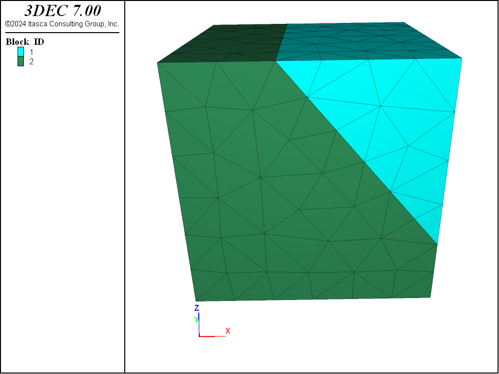
Figure 1: Example block meshed with tetrahedral zones.
IMPORTANT NOTE: The above example was exported from a model created in 3DEC and shows blocks defined by faces and zones. The faces represent the original rigid block faces prior to zoning. The blocks are therefore convex. It is possible to import zoned blocks where the blocks are not convex. In this case the * FACES section is omitted and the list of faces for each block is also omitted.
In this case, a “face block” is added to each triangular face on the outside of each block to allow the contact detection and force calculation to work. Adding faceblocks adds memory and calculation overhead, but allows you to create models with concave blocks. This is discussed in more detail in the next section.
Importing Blocks as Zones
Prior to 3DEC Version 7, it was only possible to import blocks (not zones). Complicated geometries were created by importing an assembly of tetrahedral blocks. Most of the time, most of these blocks are joined – the contacts between them are not true faults. This is very inefficient and uses up a lot of memory and slows down the computations.
In Version 7, new logic has been added to enable turning tet blocks into zones as they are imported. If the command block merge-start is given prior to creating blocks, each subsequent block create tet command will check if the group (slot sDefault) matches the group of an existing block. If it does, then a new block will not be created. Instead, a new zone will be created, and this zone will be added to the existing block.
When all the blocks are created, you will have one or more zoned blocks. The blocks may be concave. To make the contact calculations work correctly, a series of “face blocks” are added. A face block is a essentially a 2D triangular block that is created on each external face. Only the face blocks participate in the contact calculations, greatly increasing the efficiency of the program in some cases. To add the face blocks, the command block merge-finish is given after all blocks have been created.
Using the merge logic implies the following:
block zone generatecommands will not be needed since blocks will be zoned as they are createdblock joincommands are not needed- Blocks may be concave
- All blocks being imported must be tetrahedral
- You cannot cut blocks after creation
Faceblocks can be plotted and accessed with FISH (fblock functions). See Open Pit with Faceblocks for an example of importing and merging.
| Was this helpful? ... | 3DEC © 2019, Itasca | Updated: Feb 25, 2024 |