Impermeable Concrete Caisson Wall with Pretensioned Tiebacks
Problem Statement
Note
The project file for this example is available to be viewed/run in FLAC3D.[1] The project’s main data file is shown at the end of this example.
This example demonstrates a modeling procedure to simulate the staged construction of a vertical excavation supported by an impermeable concrete caisson wall with pretensioned tiebacks. [2] The excavation is approximately 84 m long by 36.5 m wide, and the final excavation depth is 23.5 m. The wall is 1.07 m thick and is composed of interlocking concrete caissons with a length of 26.5 m. Soldier piles are installed along the wall at 2.25 m spacing, and inclined, pretensioned tiebacks are connected to and extend from the soldier piles. Figure 1 illustrates a quarter-section of the excavation with the wall, soldier pile, and tieback support. The system of coordinate axes are defined for this example such that the origin is beneath the center of the excavation with the \(z\)-axis pointing upward. The final depth of the excavation is at \(z\) = 26.5 m, and the ground surface is at \(z\) = 50 m.
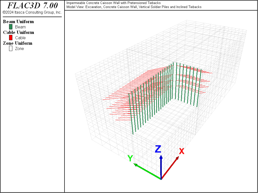
Figure 1: Excavation with concrete caisson wall including soldier piles and inclined tiebacks (quarter-section view).
The purpose of this analysis is to evaluate the stability of the excavation in terms of the displacement of the wall and the development of forces in the tiebacks. The analysis is performed as follows.
- Initial equilibrium is established with the concrete wall and soldier piles installed to a depth of 26.5 m prior to excavation. The initial state includes the pore pressure distribution accounting for the water table at elevation \(z\) = 39.5 m and the impermeable wall. The \(K_0\) value (coefficient of earth pressure at rest) for this problem is 0.6.
- The excavation is made in five cuts. The excavation depths for each cut are summarized in Table 1. The zones associated with each cut are labeled in Figure 2.
Table 1: Excavation Depths Cut Excavation Depth (m) 1 3.5 2 8.0 3 13.0 4 17.5 5 23.5
- After each of the first four cuts, a row of tiebacks is installed, and these tiebacks are pretensioned before the next cut is made.
- Cuts 3 through 5 are below the water level. Before each of these cuts, the excavation is dewatered to 1 m below the excavation depth for that cut. The zones associated with each dewatering step are labeled in Figure 2.
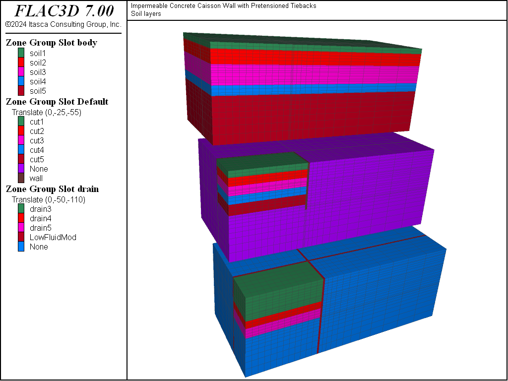
Figure 2: Group names applied to zones in the Building Block and Model panes.
There are two aspects of this example that are highlighted.
First, the tiebacks are pretensioned using the structure cable apply tension command, which assigns an axial force
to the ungrouted cable elements while the model is cycled to equilibrium.
Second, the procedure to simulate dewatering uses the fluid flow calculation in FLAC3D
to produce a pore-pressure distribution that closely corresponds to the boundary conditions applied for the dewatering stage.
This approach provides pore pressures around the excavation that are expected
to reflect the field condition better than using the zone water command will.
The zone water command does not provide as precise a calculation
for pore pressures in the vicinity of the wall as the flow calculation.
The stratigraphy consists of five horizontal soil layers of different thicknesses. The soils are shown in Figure 2, and the soil properties are summarized in Table 2.
The initial water level is located 10.5 m below the ground surface (\(z\) = 39.5 m), near the top of Soil 3.
| Soil 1 | Soil 2 | Soil 3 | Soil 4 | Soil 5 | |
|---|---|---|---|---|---|
| Thickness (m) | 3.0 | 7.0 | 10.0 | 5.0 | 25.0 |
| Dry density (kg/m3) | 1830 | 2000 | 2050 | 2100 | 2250 |
| Bulk modulus (MPa) | 25.0 | 81.9 | 147.0 | 333.0 | 833.0 |
| Shear modulus (MPa) | 11.6 | 37.8 | 68.0 | 154.0 | 625.0 |
| Cohesion (MPa) | 0.025 | 0.0 | 0.0 | 0.35 | 15.0 |
| Friction angle (degrees) | 26 | 34 | 38 | 42 | 45 |
| Dilation angle (degrees) | 0 | 2 | 5 | 5 | 0 |
| Mobility coefficient (m2/(Pa-sec)) | 10-7 | 10-7 | 10-7 | 10-7 | 10-7 |
| Porosity | 0.18 | 0.18 | 0.13 | 0.15 | 0.15 |
The properties of the concrete wall, soldier piles, and tiebacks are summarized in Table 3, Table 4, and Table 5, respectively. The soldier piles are located at a spacing of 2.25 m along the wall. Four rows of tiebacks are installed and connected to the soldier piles during construction. The tiebacks have an inclination of approximately 25° and are pretensioned after installation at the loads listed in Table 5.
| Thickness (m) | 1.07 |
| Density (kg/m3) | 2500 |
| Young’s modulus (GPa) | 25.0 |
| Poisson’s ratio | 0.4 |
| Cohesion (MPa) | 4.0 |
| Friction angle (degrees) | 45 |
| Tensile strength (MPa) | 2.0 |
| Area (m2) | 0.0144 |
| Spacing (m) | 2.25 |
| Young’s modulus (GPa) | 205.0 |
| Poisson’s ratio | 0.3 |
| Moment of inertia (m4) | 8.75 × 10⁻⁴ |
| Row 1 | Row 2 | Row 3 | Row 4 | |
|---|---|---|---|---|
| Area (m2) | 0.00554 | 0.00554 | 0.00554 | 0.00554 |
| Total length (m) | 21.897 | 19.691 | 17.187 | 14.398 |
| Bonded length (m) | 12.0 | 12.0 | 12.0 | 12.0 |
| Pretension (MN) | 0.80 | 0.90 | 1.15 | 1.15 |
| Spacing (m) | 2.25 | 2.25 | 2.25 | 2.25 |
| Young’s modulus (GPa) | 205.0 | 205.0 | 205.0 | 205.0 |
| Tensile yield strength (MN) | 1.534 | 1.534 | 1.534 | 1.534 |
| Bond stiffness (MN/m/m) | 560.0 | 560.0 | 560.0 | 560.0 |
| Bond strength (MN/m) | 0.15 | 0.15 | 0.15 | 0.15 |
| Bond friction (degrees) | 25 | 25 | 25 | 25 |
Modeling Procedure
A FLAC3D model of a quarter-section of the excavation is created using the Building Block pane, as shown in Figure 2. The model contains a coarse mesh and short distances to model boundaries in order to speed the calculation for demonstration purposes. The soil layers are assigned names using the Building Block pane, and the Model pane is used to assign names to the excavation sequence and dewatering sequence.
The fluid-flow configuration is used in this analysis in order to simulate the excavation
dewatering. The soil properties in Table 2 are entered as
the “dry” properties. Saturated properties (e.g., wet densities) are calculated automatically in
the fluid-flow configuration. The pore pressure is initialized using the zone water
command. The in-situ stress state is obtained by the command zone initialize-stresses,
provided that the zone density, saturation, and porosity as well as the pore pressure have been
assigned.
The concrete wall is added at the initial stage by assigning the material properties in
Table 3 to zones at the location of the wall. See
Figure 2. In order to model the wall as impermeable, the fluid null model
(zone fluid cmodel assign null) is assigned to the wall zones, and the porosity
and pore pressures in these zones are set to zero. (By setting the porosity to zero, the bulk
density will not be affected.) Note that the addition of the wall is done in two steps. First,
the wall is made impermeable and the model is equilibrated. Then, the mechanical properties of
the wall zones are changed and the model is equilibrated again. In this way, the total stress
only reflects the stress change due to the weight of the wall, and the pore pressure remains
hydrostatic around the wall. The initial pore pressure distribution for the model with the wall
in place is shown in Figure 3.
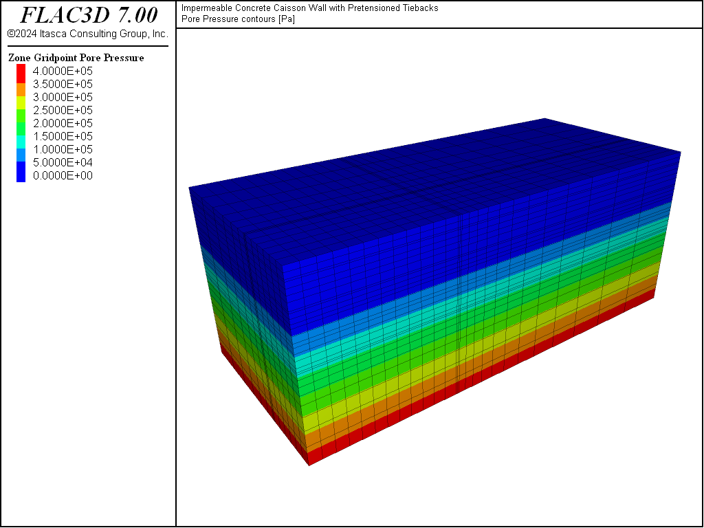
Figure 3: Initial pore pressure distribution.
The FISH function createStructure defined in the file “struct-geometry.dat” lays out positions of the soldier piles and cable tiebacks using the geometry logic in the set structure. This description could just as easily have been imported as CAD data.
The soldier piles are also installed at this stage using structural beam elements, using the
structure beam import from-geometry command. The soldier piles are created at 2.25 m spacing
within the wall zones. By using beam elements, the soldier piles are rigidly connected to the wall
zones at the beam nodes. The soldier pile locations are indicated by the vertical lines in
Figure 4.
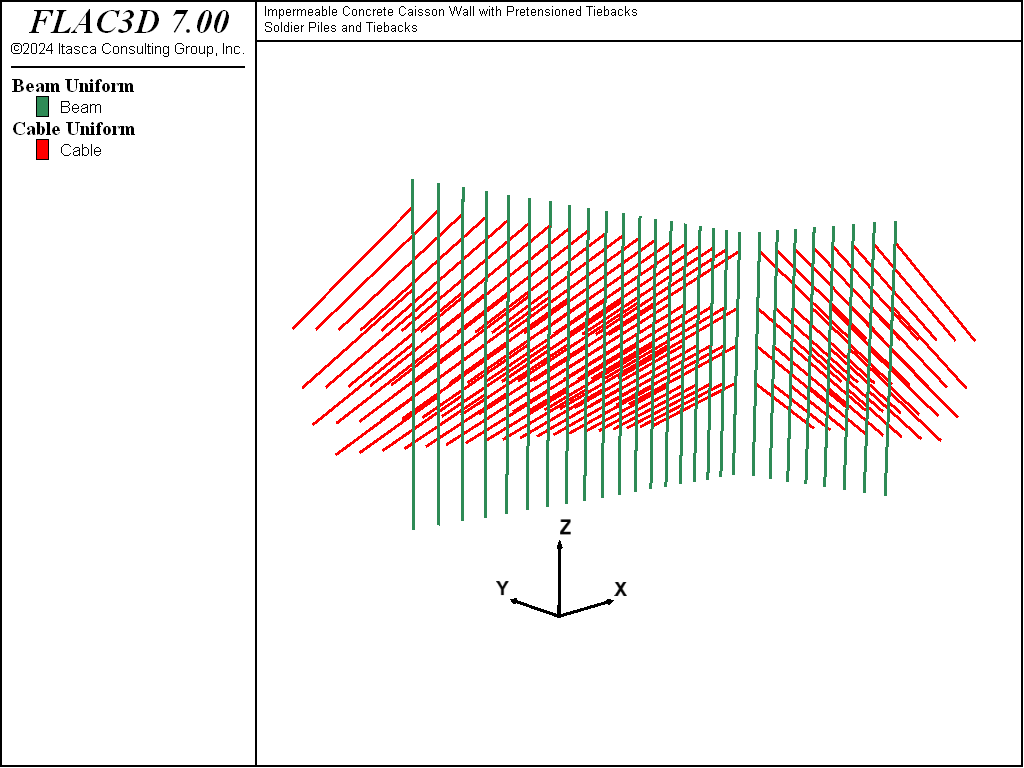
Figure 4: Locations of soldier piles (vertical lines) and tiebacks (inclined lines).
The excavation cuts are made by nulling zones within a cut region. The “excavation” is done incrementally by nulling zones in stages within each cut. In this way, transient effects on model response are minimized.
A row of tiebacks is added after each cut by using the structure cable import from-geometry
command in two steps representing the ungrouted and grouted sections. Note that the snap
keyword is used during creation to ensure that the end nodes fall in the same location as an existing
beam or cable node, and the structure node join command is used to create rigid links between
nodes in the same location, ensuring that the tiebacks are linked to the soldier piles and that
each tieback segment is connected. The tieback geometry is shown in Figure 4.
A row of tiebacks is installed after each stage. After the tiebacks are created, they are assigned
properties as listed in Table 5. Note that the tieback segment
closest to the soldier pile is unbonded (structure cable property grout-cohesion 0.0).
The tiebacks are pretensioned using the command structure cable apply tension on the ungrouted
portion. The model is then cycled to equilibrium, and the applied axial force condition is made
inactive. The axial force in these elements will remain, but after the condition is inactivated, the
elements will respond normally to changes.
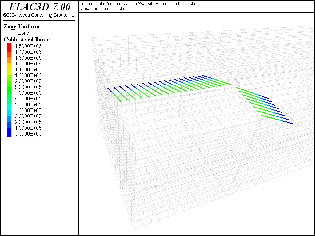
Figure 5: Axial forces in the first row of tiebacks after pretensioning.
Dewatering is simulated for Cuts 3, 4, and 5 by setting the pore pressure to zero over the drained depth, 1 m below the excavation depth for each cut. The model response to dewatering is calculated in two steps. First, a fluid flow-only calculation is made to bring the model to a steady-flow state for the changed pore-pressure condition. Then, a mechanical-only calculation (with fluid modulus set to zero to prevent additional generation of pore pressure) is made. Figure 6, 7, and 8 show the pore pressure distributions after dewatering for Cuts 3, 4, and 5.
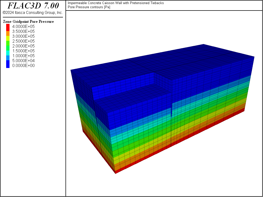
Figure 6: Pore pressure distribution after dewatering for Cut 3.
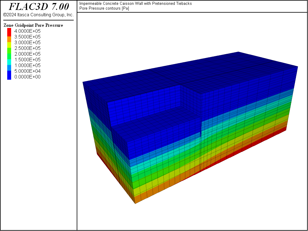
Figure 7: Pore pressure distribution after dewatering for Cut 4.
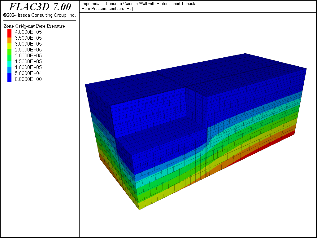
Figure 8: Pore pressure distribution after dewatering for Cut 5.
Results
The results of this example simulation are presented below in a series of plots indicating the development of axial forces in the tiebacks and the displacements in the soils and wall as the excavation cuts progress.
Figure 9 through Figure 12 plot the axial forces in the tiebacks. These plots present a view normal to the \(x\)-axis. The maximum axial force is found to develop in the third row of tiebacks along the wall parallel to the \(x\)-axis. The maximum value is approximately 1.3 MN at Cuts 4 and 5.
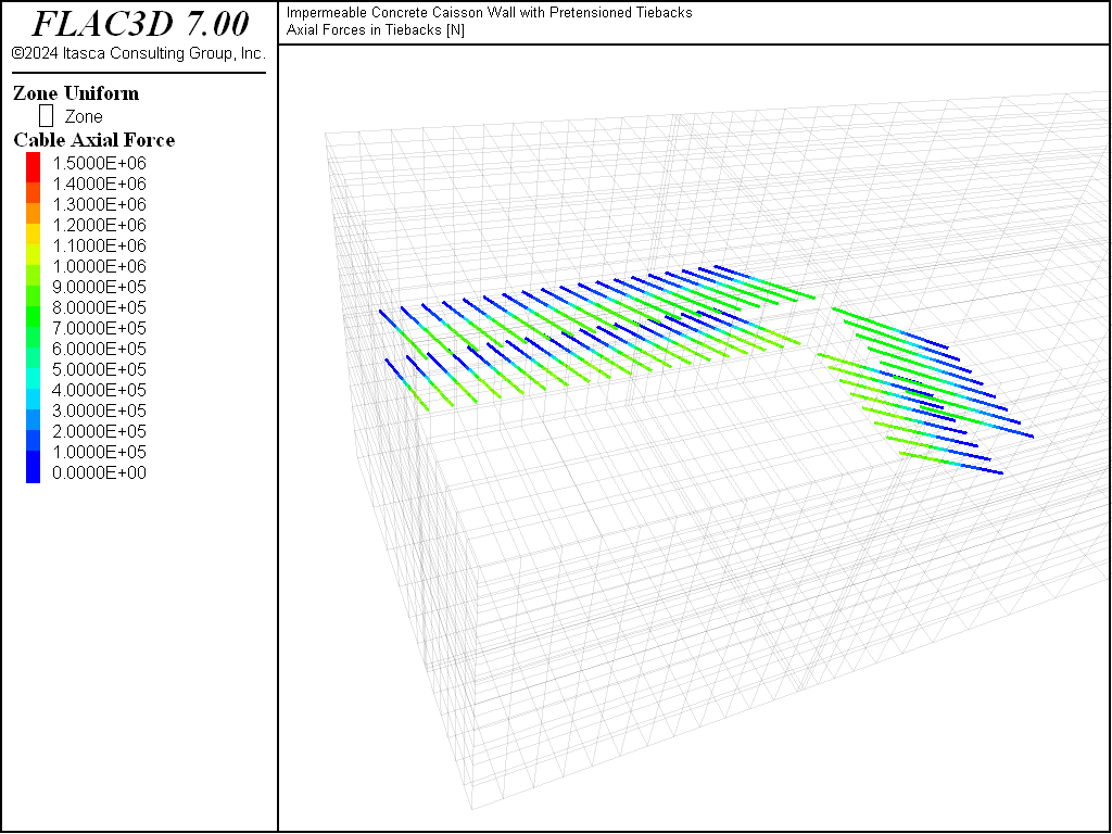
Figure 9: Axial forces in tiebacks after Cut 2.
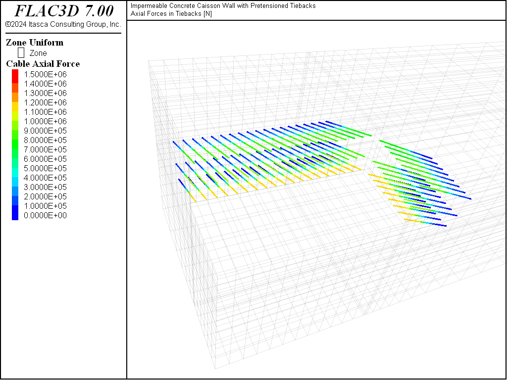
Figure 10: Axial forces in tiebacks after Cut 3.

Figure 11: Axial forces in tiebacks after Cut 4.
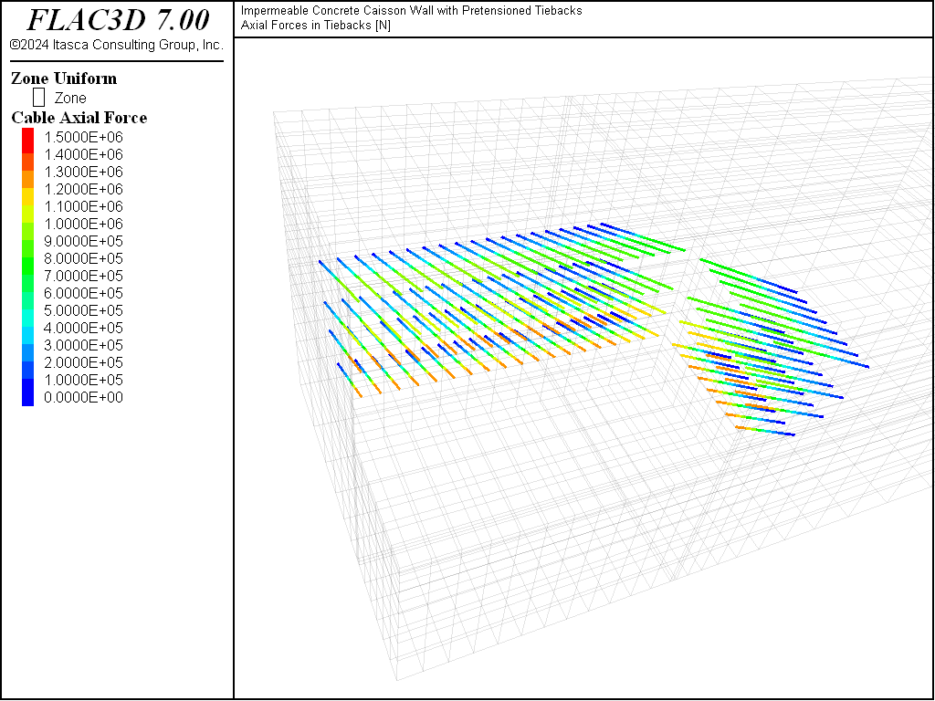
Figure 12: Axial forces in tiebacks after Cut 5.
The displacements induced by the excavation are shown in Figure 13 through Figure 17. The maximum displacement occurs at mid-height of the wall parallel to the \(x\)-direction and is approximately 8.1 mm into the excavation after Cut 5 is completed, as shown in Figure 17. This roughly coincides with the third level of tiebacks that experience the highest tensile load. Figure 18 shows displacement histories recorded throughout the entire simulation at two locations that coincide with the maximum displacement locations on each wall. The top two lines on the plot correspond to vertical displacements, and the bottom two lines correspond to horizontal displacements. The dewatering stages appear as the horizontal line segments. Excavations follow the dewatering stages, and the walls move into the excavation up until the cable pretensioning occurs, which is indicated by the short upward trends on the two bottom lines in the history plot.
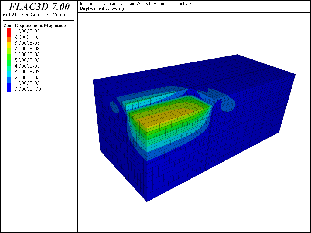
Figure 13: Displacement contours after Cut 1.
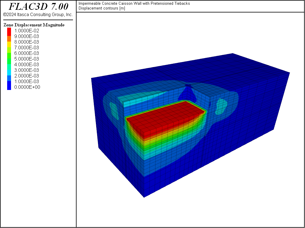
Figure 14: Displacement contours after Cut 2.
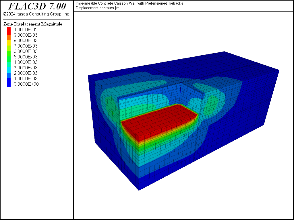
Figure 15: Displacement contours after Cut 3.
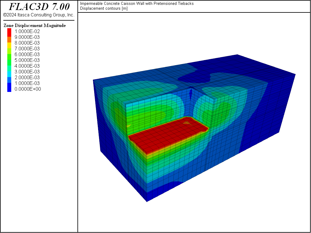
Figure 16: Displacement contours after Cut 4.
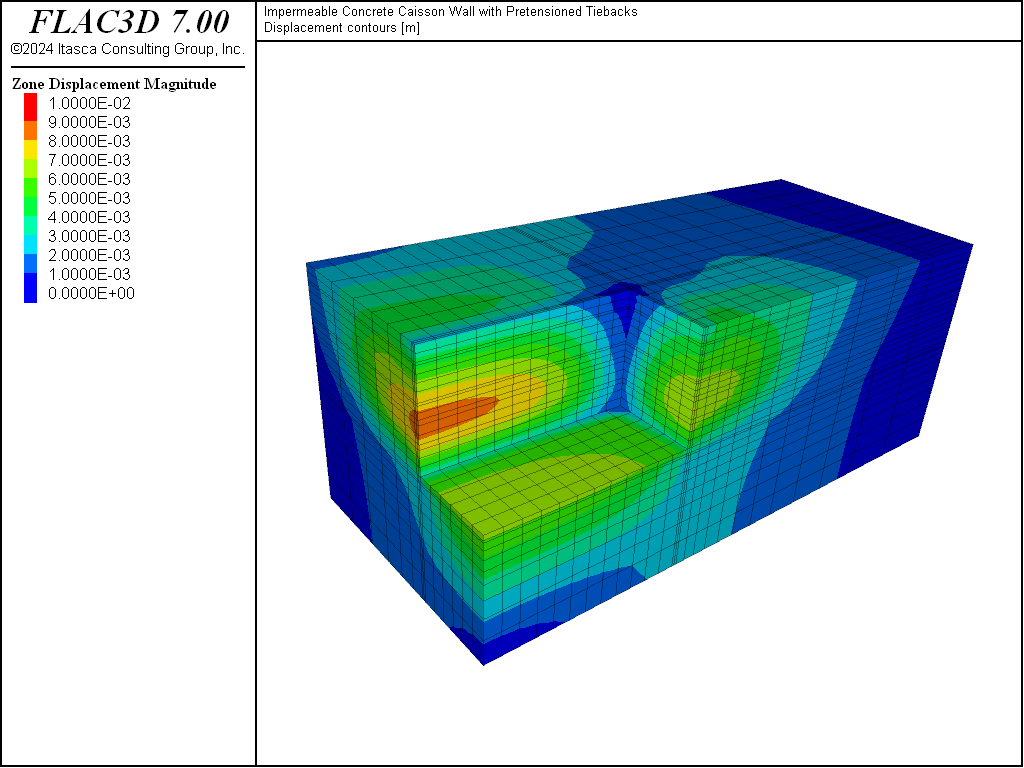
Figure 17: Displacement contours after Cut 5.
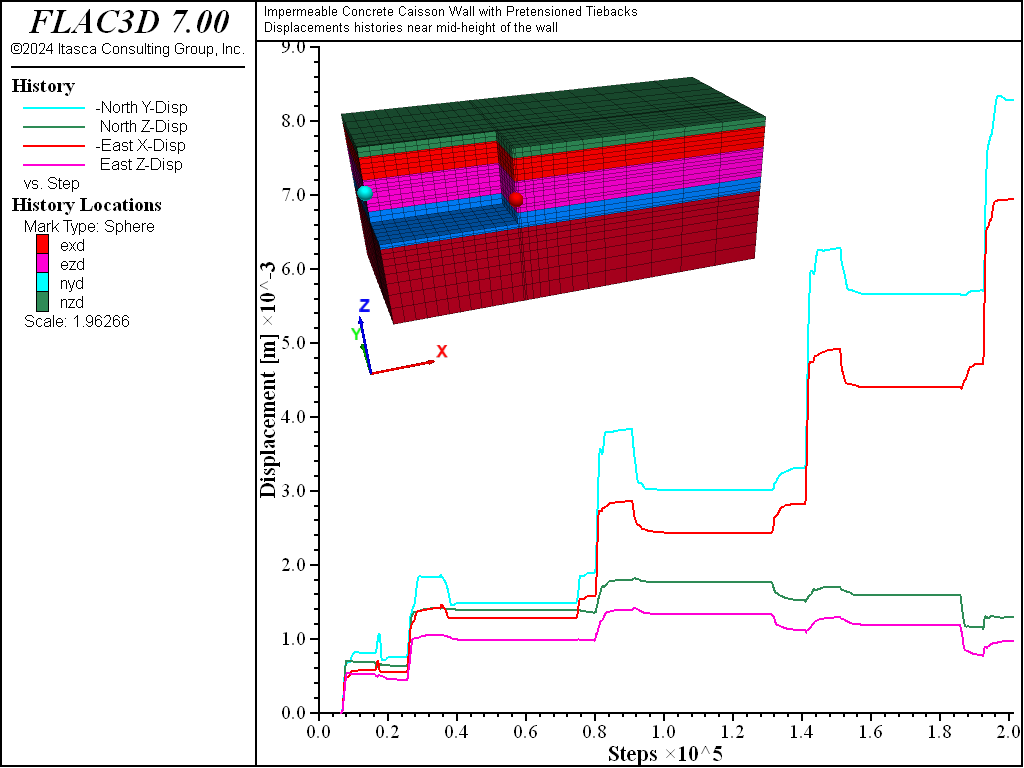
Figure 18: Displacement histories near the mid-height of the walls where maximum displacement occurs.
Data Files
CaissonWithTiebacks.dat
model new
model title 'Impermeable Concrete Caisson Wall with Pretensioned Tiebacks'
fish automatic-create off
model configure fluid
model large-strain off
; Model Geometry created interactively in Building Blocks,
; exported using State Pane
program call 'geometry' suppress
zone generate from-building-blocks
; Name areas interactively in Model Pane, exported using State Pane
program call 'names' suppress
zone face skin ; Apply names to model boundaries
; Create geometry of cables and beams,
; here using FISH but could import from CAD.
program call 'struct-geometry' suppress
model save 'grid'
; initialize the model, including boundary conditions,
; stresses, and pore-pressures
program call 'initialize'
; install the wall
program call 'install-wall'
; install beams
program call 'install-beam'
; excavation stages
program call 'stage1'
program call 'stage2'
program call 'stage3'
program call 'stage4'
program call 'stage5'
initialize.dat
;--------------------------------------
; Find initial equilibrium for the model
;--------------------------------------
model restore 'grid'
model gravity 9.81
; Boundary conditions - roller boundaries
zone face apply velocity-normal 0 range group 'Bottom'
zone face apply velocity-normal 0 range group 'East' or 'West'
zone face apply velocity-normal 0 range group 'North' or 'South'
; mechanical model and properties
zone cmodel assign mohr-coulomb
zone property bulk 2.50e7 shear 1.16e7 friction 26 cohesion 2.5e4 ...
              dilation 0 tension 1e10 density 1830 range group 'soil1'
zone property bulk 8.19e7 shear 3.78e7 friction 34 cohesion 0     ...
              dilation 2 tension 1e10 density 2000 range group 'soil2'
zone property bulk 1.47e8 shear 6.80e7 friction 38 cohesion 0     ...
              dilation 5 tension 1e10 density 2050 range group 'soil3'
zone property bulk 3.33e8 shear 1.54e8 friction 42 cohesion 3.5e5 ...
              dilation 5 tension 1e10 density 2100 range group 'soil4'
zone property bulk 8.33e8 shear 6.25e8 friction 45 cohesion 1.5e7 ...
              dilation 0 tension 1e10 density 2250 range group 'soil5'
; fluid model and properties
zone fluid cmodel assign isotropic
zone initialize fluid-density 1000
zone gridpoint initialize fluid-modulus 0
zone gridpoint initialize fluid-tension -1e-3
zone fluid property permeability 1e-7
zone fluid property porosity 0.18 range group 'soil1' or 'soil2'
zone fluid property porosity 0.13 range group 'soil3'
zone fluid property porosity 0.15 range group 'soil4'
zone fluid property porosity 0.05 range group 'soil5'
; Initial pore-pressure and saturation - water level 39.5
zone water density 1000
zone water plane normal (0,0,1) origin (0,0,39.5)
zone gridpoint initialize saturation 0 range position-z 39.5 50
zone gridpoint fix pore-pressure 0 range position-z 39.5 tol 0.1
; Initialize stress state due to gravity
zone initialize-stress ratio 0.6
; Cycle to make certain you reach equilibrium
model fluid active off
model solve elastic ratio-local 1e-3
; Save initial state for reference
model save 'initial'
install-wall.dat
;--------------------------------------
; Install the impermeable concrete wall
;--------------------------------------
model restore 'initial'
; Reset displacement and velocity field for reference
zone gridpoint initialize displacement (0,0,0)
zone gridpoint initialize velocity     (0,0,0)
; --- concrete wall installation ---
; First change fluid properties to impermeable
zone fluid property porosity 0            range group 'wall'
zone gridpoint initialize pore-pressure 0 range group 'wall'
zone fluid cmodel assign null             range group 'wall'
model solve ratio-local 1e-3
; Change mechanical properties
zone property tension 0.0
zone property density 2500 young 2.5e10 poisson 0.4 friction 45 ...
              cohesion 4e6 tension 2e6 range group 'wall'
model solve ratio-local 1e-3
model save 'wall'
install-beam.dat
;---------------------
; Create solider beams
;---------------------
model restore 'wall'
zone gridpoint initialize displacement (0,0,0)
zone gridpoint initialize velocity     (0,0,0)
struct beam import from-geometry 'structure' segments 13 range group 'beam'
structure beam property young 2.05e11 poisson 0.3
structure beam property cross-sectional-area 1.44e-2 ...
                        moi-z 875e-6 moi-y 875e-6 moi-polar 0.0
;
model solve ratio-local 1e-3
model save 'beam'
stage1.dat
model restore 'beam'
; Reset displacements and velocities for reference
zone gridpoint initialize displacement (0,0,0)
zone gridpoint initialize velocity     (0,0,0)
; --- histories ---
; North side of excavation
zone history name 'nyd' displacement-y position (0, 18.283, 36)
zone history name 'nzd' displacement-z position (0, 18.283, 36)
; East side of excavation
zone history name 'exd' displacement-x position (42.0715, 0, 34.25)
zone history name 'ezd' displacement-z position (42.0715, 0, 34.25)
; --------------------------
; -   EXCAVATION STAGE 1   -
; --------------------------
; --- above water level, no need to drain, but fix that line for stability ---
; --- excavate cut1
zone cmodel assign null range group 'cut1'
model solve ratio-local 1e-3
model save 'excavation-1'
; --- first level of tie-backs ---
struct cable import from-geometry 'structure' segments 5 snap ...
       group 'cable1-1' range group 'cable1-1'
struct cable import from-geometry 'structure' segments 10 snap ...
       group 'cable1-2' range group 'cable1-2'
struct node join range group 'cable1-1' ; Connect ungrouted cables to soldier
                                        ; beams and grouted cables rigidly
struct cable property young 2.05e11 yield-compression 1.0e5 ...
                      yield-tension 15.34e5 cross-sectional-area 5.54e-3
struct cable property grout-cohesion   0.0 grout-friction  0.0 ...
                      grout-stiffness  0.0 range group 'cable1-1'
struct cable property grout-cohesion 1.5e5 grout-friction 25.0 ...
                      grout-stiffness 0.56e9 grout-perimeter 0.264 ...
                      range group 'cable1-2'
; Pretension the tiebacks
struct cable apply tension value 8e5 range group 'cable1-1'
model solve ratio-local 1e-3
struct cable apply tension active off
model save 'stage-1'
stage2.dat
model restore 'stage-1'
; --------------------------
; -   EXCAVATION STAGE 2   -
; --------------------------
; --- above water level (_drain2 > _wt), no need to drain ---
; --- excavate in stages ---
zone cmodel assign null range group 'cut2'
model solve ratio-local 1e-3
model save 'excavation-2'
; --- second level of tie-backs ---
struct cable import from-geometry 'structure' segments 5 snap ...
       group 'cable2-1' range group 'cable2-1'
struct cable import from-geometry 'structure' segments 10 snap ...
       group 'cable2-2' range group 'cable2-2'
struct node join range group 'cable2-1' ; Connect ungrouted cables to soldier
                                        ; beams and grouted cables rigidly
struct cable property young 2.05e11 yield-compression 1.0e5 ...
                      yield-tension 15.34e5 cross-sectional-area 5.54e-3
struct cable property grout-cohesion   0.0 grout-friction  0.0 ...
                      grout-stiffness  0.0 range group 'cable2-1'
struct cable property grout-cohesion 1.5e5 grout-friction 25.0 ...
                      grout-stiffness 0.56e9 grout-perimeter 0.264 ...
                      range group 'cable2-2'
; Pretension the tiebacks
struct cable apply tension value 9e5 range group 'cable2-1'
model solve ratio-local 1e-3
struct cable apply tension active off
model save 'stage-2'
stage3.dat
model restore 'stage-2'
; --------------------------
; -   EXCAVATION STAGE 3   -
; --------------------------
; --- drain 1m below base of excavation ---
; (flow first)
model fluid active on
model mechanical active off
zone gridpoint fix pore-pressure 0 range group 'drain3'
zone fluid cmodel assign null range group 'drain3'
zone gridpoint initialize fluid-modulus 20
zone gridpoint initialize fluid-modulus 2 range group 'LowFluidMod'
model solve fluid ratio-flow 1e-4
model save 'drain-fluid-3'
; (mech next)
model fluid active off
model mechanical active on
zone gridpoint initialize fluid-modulus 0
model solve ratio-local 1e-3
model save 'drain-mech-3'
; --- excavate in stages ---
zone cmodel assign null range group 'cut3'
model fluid active off
model mechanical active on
model solve ratio-local 1e-3
model save 'excavation-3'
; --- third level of tie-backs ---
struct cable import from-geometry 'structure' segments 5 snap ...
       group 'cable3-1' range group 'cable3-1'
struct cable import from-geometry 'structure' segments 10 snap ...
       group 'cable3-2' range group 'cable3-2'
struct node join range group 'cable3-1' ; Connect ungrouted cables to soldier
                                        ; beams and grouted cables rigidly
struct cable property young 2.05e11 yield-compression 1.0e5 ...
                      yield-tension 15.34e5 cross-sectional-area 5.54e-3
struct cable property grout-cohesion   0.0 grout-friction  0.0 ...
                      grout-stiffness  0.0 range group 'cable3-1'
struct cable property grout-cohesion 1.5e5 grout-friction 25.0 ...
                      grout-stiffness 0.56e9 grout-perimeter 0.264 ...
                      range group 'cable3-2'
; Pretension the tiebacks
struct cable apply tension value 11.5e5 range group 'cable3-1'
model solve ratio-local 1e-3
struct cable apply tension active off
model save 'stage-3'
stage4.dat
model restore 'stage-3'
; --------------------------
; -   EXCAVATION STAGE 4   -
; --------------------------
; --- drain 1m below base of excavation ---
; (flow first)
model fluid active on
model mechanical active off
zone gridpoint fix pore-pressure 0 range group 'drain4'
zone fluid cmodel assign null range group 'drain4'
zone gridpoint initialize fluid-modulus 20
zone gridpoint initialize fluid-modulus 2 range group 'LowFluidMod'
model solve fluid ratio-flow 1e-4
model save 'drain-fluid-4'
; (mech next)
model fluid active off
model mechanical active on
zone gridpoint initialize fluid-modulus 0
model solve ratio-local 1e-3
model save 'drain-mech-4'
; --- excavate in stages ---
zone cmodel assign null range group 'cut4'
model fluid active off
model mechanical active on
model solve ratio-local 1e-3
model save 'excavation-4'
; --- fourth level of tie-backs ---
struct cable import from-geometry 'structure' segments 5 snap ...
       group 'cable4-1' range group 'cable4-1'
struct cable import from-geometry 'structure' segments 10 snap ...
       group 'cable4-2' range group 'cable4-2'
struct node join range group 'cable4-1' ; Connect ungrouted cables to soldier
                                        ; beams and grouted cables rigidly
struct cable property young 2.05e11 yield-compression 1.0e5 ...
                      yield-tension 15.34e5 cross-sectional-area 5.54e-3
struct cable property grout-cohesion   0.0 grout-friction  0.0 ...
                      grout-stiffness  0.0 range group 'cable4-1'
struct cable property grout-cohesion 1.5e5 grout-friction 25.0 ...
                      grout-stiffness 0.56e9 grout-perimeter 0.264 ...
                      range group 'cable4-2'
; Pretension the tiebacks
struct cable apply tension value 11.5e5 range group 'cable4-1'
model solve ratio-local 1e-3
struct cable apply tension active off
model save 'stage-4'
stage5.dat
model restore 'stage-4'
; --------------------------
; - FINAL EXCAVATION STAGE -
; --------------------------
; --- drain 1m below base of excavation ---
; (flow first)
model fluid active on
model mechanical active off
zone gridpoint fix pore-pressure 0 range group 'drain5'
zone fluid cmodel assign null range group 'drain5'
zone gridpoint initialize fluid-modulus 20
zone gridpoint initialize fluid-modulus 2 range group 'LowFluidMod'
model solve fluid ratio-flow 1e-4
model save 'drain-fluid-5'
; (mech next)
model fluid active off
model mechanical active on
zone gridpoint initialize fluid-modulus 0
model solve ratio-local 1e-3
model save 'drain-mech-5'
; --- excavate in stages ---
zone cmodel assign null range group 'cut5'
model fluid active off
model mechanical active on
model solve ratio-local 1e-3
model save 'stage-5'
Endnotes
| [1] | To view this project in FLAC3D, use the program menu.
⮡ FLAC |
| [2] | This example application is derived from a demonstration model prepared in collaboration with Matthew Janes, Isherwood Associates, Mississauga, Ontario, Canada. |
| Was this helpful? ... | 3DEC © 2019, Itasca | Updated: Feb 25, 2024 |