Simulation of Pull-Tests for Fully Bonded Rock Reinforcement
Problem Statement
Note
The project file for this example is available to be viewed/run in FLAC3D.[1] The project’s main data file is shown at the end of this example.
The most common method to determine properties for fully bonded rock reinforcement (such as grouted cable bolts, resin-grouted steel rebar, or rockbolts) is to perform pull-tests on small segments of grouted reinforcement in the field. Typically, segments 50 cm in length or longer are grouted into boreholes. The ends of these segments are pulled with a jack mounted to the surface of the tunnel and connected to cable via a barrel-and-wedge-type anchor. The force applied to the reinforcement and the deformation of the reinforcement are plotted to produce an axial force-deflection curve. From this curve, the peak shear strength of the grout bond is determined. The results for pull-tests on one-half meter segments of several types of cables are illustrated in Figure 1. These plots are expressed in terms of tons/m versus deformation in mm.
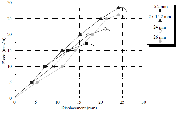
Figure 1: Field results for pull-tests on various types of cables for a bond length of 0.5 m and a water/cement ratio of 1/3.
In this example application, FLAC3D is used to model pull-tests of this type. Two different approaches are available to simulate pull-tests using the structural elements in FLAC3D:
- cable elements, which assume the grout behaves as an elastic-perfectly plastic material with confining stress dependence but no loss of strength after failure; and
- modified pile elements, which account for changes in confining stress, strain-softening behavior of the grout, and rupture of the reinforcement.
One additional advantage of using the modified pile elements to model reinforcement behavior is that bending moment resistance can be included. This behavior is needed when the reinforcement is subjected to shearing, as described later in Pull-Test with Tensile Rupture and Shear Test on Rockbolts.
The purpose of the following examples is to demonstrate the use and capabilities of both approaches.
Approach 1: Modeling Rock Reinforcement Using Cable Elements
In the following sections, the pull-tests are simulated using the cable-element logic. The commands needed to create and view variables associated with cable elements are described in Cable Commands.
Pull-out Strength without Confinement
First, we consider the case where the confining stress dependence on the reinforcement shear-bond strength may be neglected. The cable properties required by FLAC3D’s cable-bolt model must be extracted from the field pull-test curve. This is easily done when the field test data are presented in terms of force/unit length versus deformation, as shown in Figure 1. Assuming no yielding in the cable, the value of the grout shear stiffness, grout-stiffness, is simply the slope of the curve, with the ultimate bond strength, grout-cohesion, being the peak-pull strength value per unit length. This assumption is justified by the fact that the steel normally yields at stresses that are higher than those corresponding to the pull-out forces, as shown in Figure 1. For example, for a representative cable of 15 mm diameter and 0.5 m length and an (admissible) yield strength of 1200 MPa (assumed in the FLAC3D models in the following sections), the maximum yield force is 212 kN. This value is approximately 50% greater than the highest pull-out force of 28 tons/m × 0.5 = 140 kN, at which the grout fails in Figure 1. In addition, in these examples, the compliance of the reinforcement element and the rock are neglected relative to the compliance of the grout.
For example, all of the pull-test results shown here have roughly the same loading slope, so an average value of grout-stiffness is chosen for all:
This value of grout-stiffness is very low, indicating a rather poor grouting job for the cable. Typical grout-stiffness values would be approximately one order of magnitude or more higher than this.
The value of grout-cohesion for the single 15.2 mm wire is simply the peak shear resistance in tons/m. In this case, grout-cohesion \(\approx\) 17.5 tons/m, or 17.5 × 10⁴ N/m. To check whether this value of grout-cohesion is reasonable, it can be converted to grout shear strength by dividing by the approximate surface area of the wire (assuming the bond fails at the grout/cable interface). We find that the peak shear strength is 3.66 MPa. This value should roughly equal half the uniaxial compressive strength of the grout, indicating either a very poor grout, or that the cable was allowed to rotate during the pull-test, yielding artificially low grout shear-strength values. [2]
The data file “Pull01.dat” is a simple representation of a pull-test using FLAC3D. The cable end-node is pulled at a small, constant \(y\)-oriented velocity—see Figure 2. A FISH function is used to sum the reaction forces and monitor nodal displacement generated by the pull-tests for comparison to field test results.
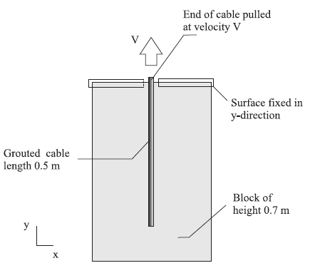
Figure 2: Sketch of geometry of FLAC3D model for pull-test.
A plot of the relation between pull force and cable displacement (histories force and disp, respectively) for the case of a single 15.2 mm cable is shown in Figure 3. This figure illustrates the general force-displacement behavior given in Figure 1. The peak force is reached at a displacement of approximately 17 mm. After this point, the cable is simply pulled out of the borehole in much the same fashion as a block sliding on a plane.
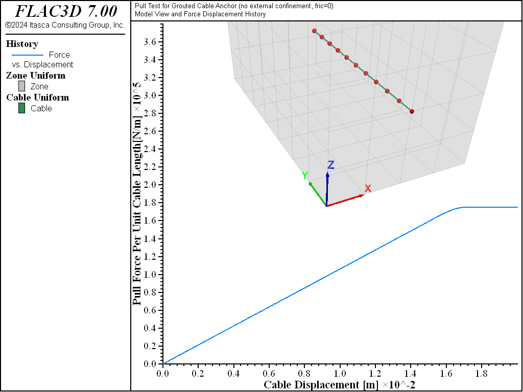
Figure 3: Pull force in N/m versus cable displacement in meters for the case of a single 15.2 mm grouted cable.
Figure 4 to 6 show the axial force distribution on the cable for displacements of 10 mm, 16.5 mm, and 17.5 mm, respectively. Note that cable-bond slip progresses rapidly after peak strength is reached at the first cable element. Superimposed on the axial forces are locations at which the grout bond is yielding. At 10 mm (Figure 4), the grout bond has not failed. At 16.5 mm (Figure 5), bond failure is initiated and rapidly propagates (Figure 6) down the entire cable length. At that stage, the force on the cable end is simply the sum of grout_cohesion × \(l_i\) (where \(l_i\) is the length of cable segments) for all \(n\)-slipping segments. If the embedded length were long enough, the cable axial force would eventually reach the yield force of the cable itself. The cable should then break when the extension strain equals the ultimate breaking strain of the cable (generally around 3%). An example illustrating tensile rupture of the element is given in Pull-Test with Tensile Rupture.
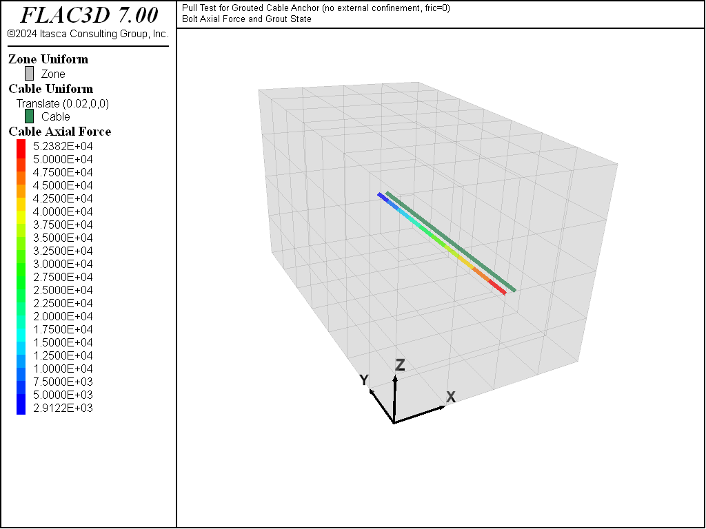
Figure 4: At 10 mm deformation: Plot of axial force and cable grout yield points for pull-test simulation on a 15.2 mm cable bolt.
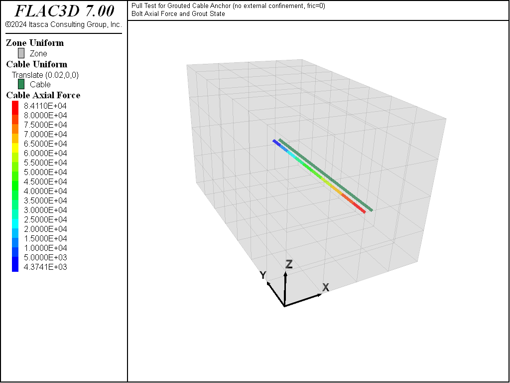
Figure 5: At 16.5 mm deformation: Plot of axial force and cable grout yield points for pull-test simulation on a 15.2 mm cable bolt.
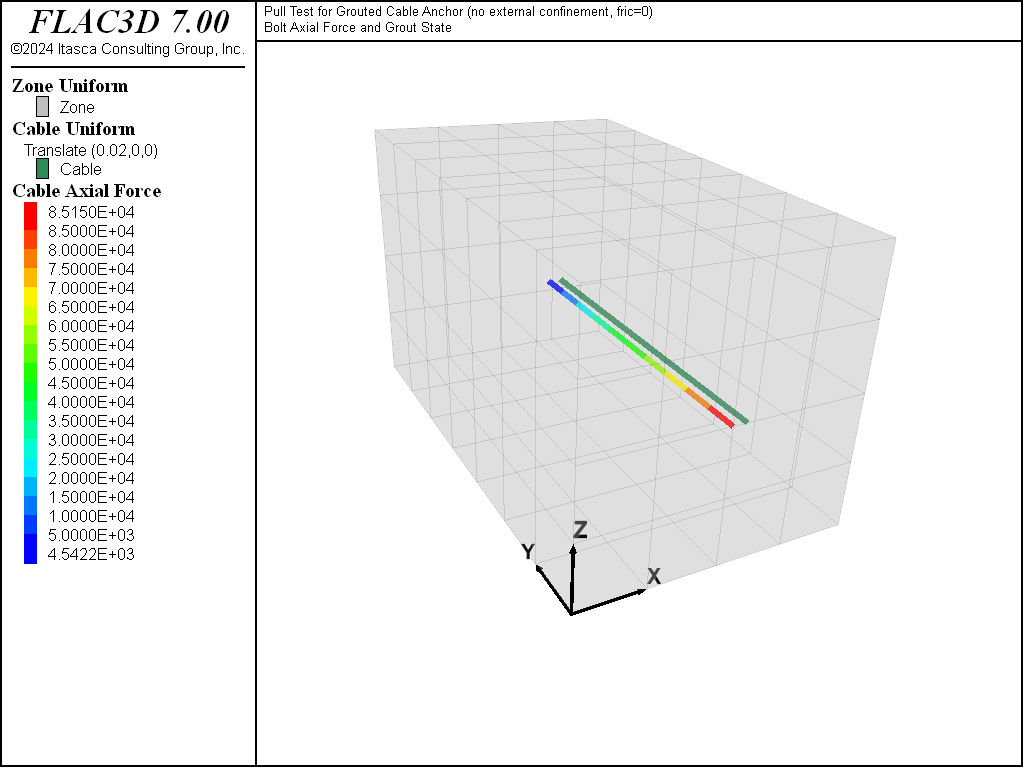
Figure 6: At 17.5 mm deformation: Plot of axial force and cable grout yield points for pull-test simulation on a 15.2 mm cable bolt.
Pull-out Strength with Confinement
The cable shear bond strength will, in general, increase with increasing effective pressure (\(p\)‘) acting on the cable. A linear law is implemented in FLAC3D whereby the cable shear bond strength is defined as a constant (grout-cohesion) plus the effective pressure on the cable multiplied by the cable perimeter (grout-permeter) times the tangent of the friction angle (grout-friction). This pressure dependence is activated automatically in FLAC3D by issuing the cable properties grout-permeter and grout-friction. Note that in this case, the input data for grout-cohesion must correspond to the shear bond strength in a cable pull-test carried out without confining pressure. Numerical results of pull-tests on the 15.2 mm cable are presented in Figure 7 and 8 for a friction angle of 30° and two levels of initial confining pressure, namely \(p\)‘ = 2 and 4 MN/m2. Compare these figures to Figure 3. These figures indicate an increasing failure level with increasing initial confining pressure, illustrating the frictional character of the cable-rock interface. Results for the pull-test with confined pressure on the 15.2 mm cable were obtained using the data files “Pull02.dat” and “Pull03.dat”.
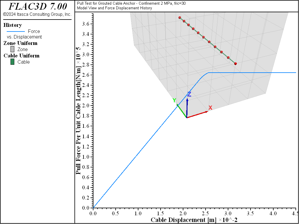
Figure 7: Pull-test on 15.2 mm cable, \(p\)‘ = 2 MN/m2.
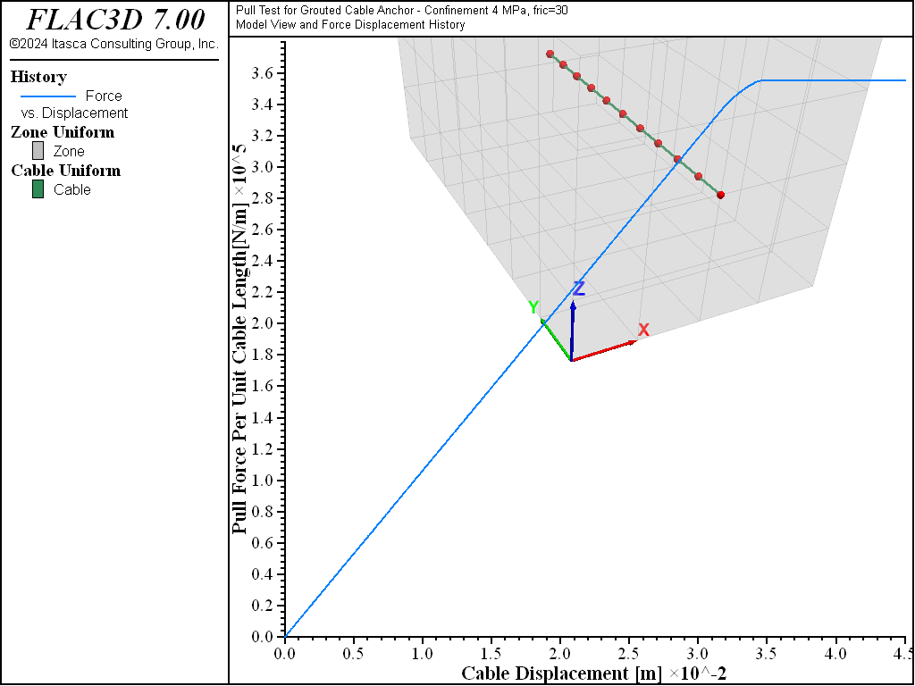
Figure 8: Pull-test on 15.2 mm cable, \(p\)‘ = 4 MN/m2.
Approach 2: Modeling Rock Reinforcement Using Modified Pile Elements
In the following sections, the modified pile-element logic in FLAC3D is used to model rock reinforcement. The purpose of the following examples is to illustrate modeling procedures with the modified pile elements. In addition to a demonstration of the features that simulate pull-tests, this section also presents examples related to the simulation of shear tests on rockbolts (see Shear Test on Rockbolts and Shear Test on Rockbolts with Rupture). The tests in this section assume that conditions are representative of a 25 mm diameter grouted bolt with grout properties the same as those defined in Pull-out Strength without Confinement.
Commands needed to create and view variables associated with the modified elements are described
in Pile Commands.
Note that the modified pile-element formulation is activated by giving the structure pile property rockbolt-flag on command.
Pull-out Strength without Confinement
The data file “Pulltest04.dat” creates a pull-test without confinement. The problem is equivalent to that described in Pull-out Strength without Confinement. Compared with the model in file “Pulltest01.dat”, the current model considers a larger diameter bolt and a free length of bolt that extends out of the block. The load is applied at the tip of the reinforcement by prescribing a constant velocity, as was done before. A FISH function, force, is used to sum the reaction forces and monitor nodal displacement generated by the pull-test.
Figure 9 represents the relation between axial force (per unit length of cable) and displacement at the tip of the bolt, for a total displacement of 20 mm. The figure shows that the maximum pull-out load is comparable to the one obtained with Approach 1 in Pull-out Strength without Confinement (the slight difference may be attributed to the different bolt size and the free length of bolt included in this model). Figure 9 also shows the default perfectly plastic behavior of the grout once the maximum cohesion is exceeded.
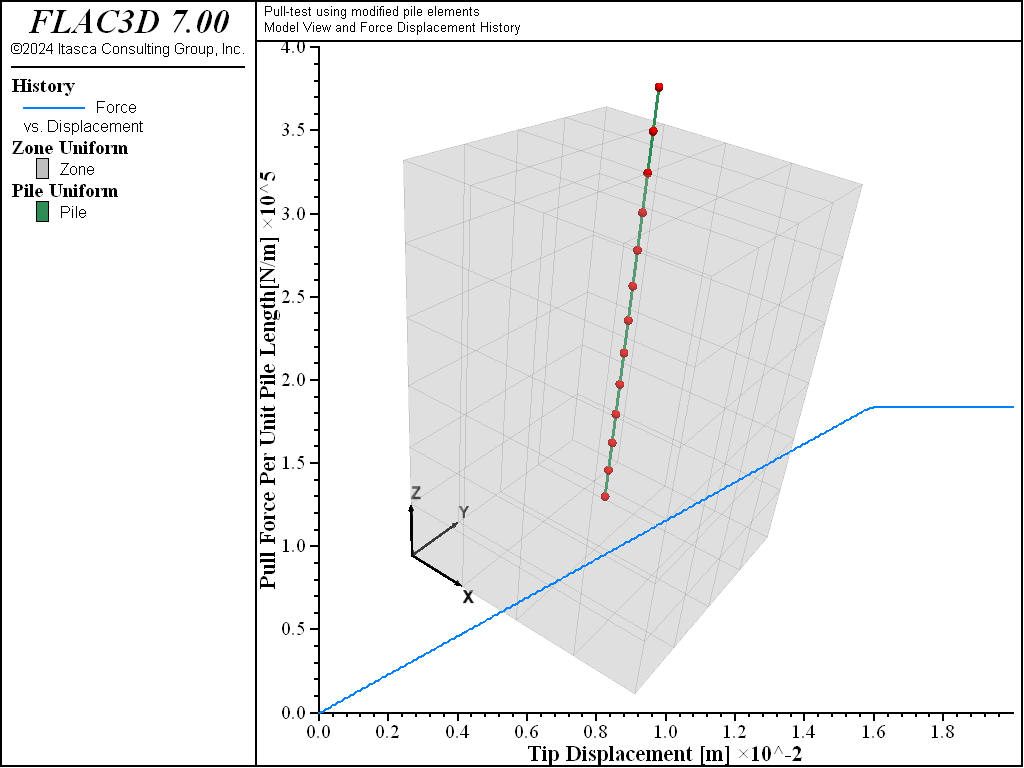
Figure 9: Pull force in N/m versus cable displacement in meters for the case of single 25 mm grouted rockbolt.
Pull-Test with Displacement Weakening
The data file “Pulltest05.dat” defines a pull-test similar to the one described in the previous section, Pull-out Strength without Confinement, but with post-peak weakening of shear bond strength. The bond strength softening of the grout is defined with the keyword coupling-cohesion-table, as described in Rockbolt Behavior. The relation between shear displacement and cohesion weakening is prescribed through table cct (Note that softening of the friction of the grout could also be defined using the keyword coupling-friction-table).
Figure 10 represents the relation between axial force (per unit length of the bonded reinforcement) and displacement at the tip of the reinforcement for a total displacement of 40 mm. The figure clearly shows the weakening of cohesion after the maximum pull-out load is reached.
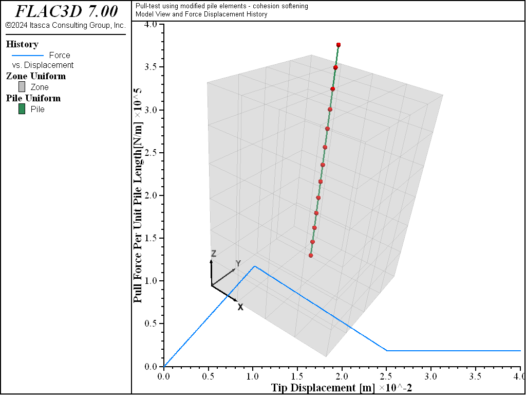
Figure 10: Pull force in N/m versus reinforcement displacement in meters for the case of a single 15.2 mm grouted reinforcement—with displacement weakening.
Pull-Test with Confinement
The data file “Pulltest06.dat” shows how a pull-test with confinement is simulated using the modified pile logic. The model is equivalent to the one discussed in Pull-out Strength with Confinement, this time for a confining stress, 4 MN/m2. As described in Behavior of Shear Coupling Springs a linear law is implemented in the modified pile logic, whereby the reinforcement shear strength is defined as a constant (coupling-cohesion-shear) plus the effective pressure on the reinforcement multiplied by the reinforcement perimeter (perimeter) times a friction angle (coupling-friction-shear). This pressure dependence is activated automatically in FLAC3D by issuing the reinforcement properties (perimeter) and (coupling-friction-shear).
Figure 11 represents the relation between axial force (per unit length of the grouted reinforcement) and displacement at the tip of the reinforcement for a total displacement of 40 mm. The results are comparable to those shown in Figure 8.
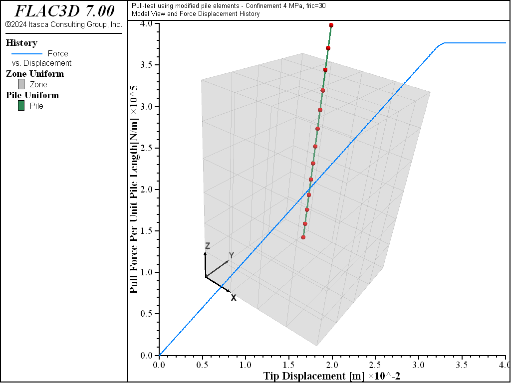
Figure 11: Pull force in N/m versus reinforcement axial displacement in meters for the case of a single 25 mm grouted bolt—uniform 4 MN/m2 confinement.
Pull-Test with Confinement — User-Defined Behavior
This example shows the use of the option coupling-confining-table to define a “mean” value \(σ_c\) of confining stress on the rockbolt for cases in which the principal stresses \(σ_x\) and \(σ_y\) perpendicular to the axis of the rockbolt are not the same.
Figure 12 shows the results obtained numerically for the relation between confining and deviatoric stresses in the case of a rockbolt with a diameter of 25 mm. In the figure, the horizontal axis represents the normalized deviatoric stress, defined as
while the vertical axis represents the normalized confining stress,
The relation was obtained from pull-test models in FLAC3D, considering different values of deviatoric stresses in the plane perpendicular to the axis bolt. The mean confining stress \(\sigma_c\) was obtained by measuring the force \(F_p\) required to pull out a bolt of length \(L\) and perimeter \(p\) with a grout of friction \(\phi\) using the expression
The data file “Pulltest07.dat” creates a model that illustrates the use of the coupling-confining-table option and the relation represented in Figure 12. The results obtained with this data file are shown in Figure 13. In this example, one of the principal stresses on the plane perpendicular to the axis of the rockbolt is zero. Note that the pull-out resistance in Figure 13 is greatly reduced compared to Figure 11 as a result of the zero stress in the lateral direction.
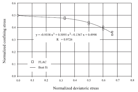
Figure 12: Example of relation between normalized confining stress and normalized deviator stress obtained numerically for a 25 mm rockbolt.
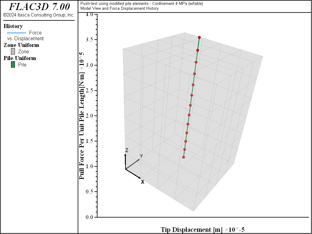
Figure 13: Rockbolt pull force in N/m versus rockbolt axial displacement in meters for the case of a single 25 mm grouted bolt—lateral confinement defined by the relationship represented in Figure 12.
Pull-Test with Tensile Rupture
This example shows the definition of limiting axial yield force and limiting axial strain for the rockbolt, using the options tensile-yield and tensile-failure-strain, respectively.
The data file “Pulltest08.dat” sets up a model that considers a limiting tensile force of 1.5 × 10⁵ N and a limiting axial strain of 1 × 10⁻⁴. The results from this model are shown in Figure 14. The diagram shows that the limiting tensile force is reached after a pull-out displacement of approximately 2.6 cm. Note that after this limiting force is reached, the pull-out force rapidly decreases to zero, indicating the rupture of the rockbolt.
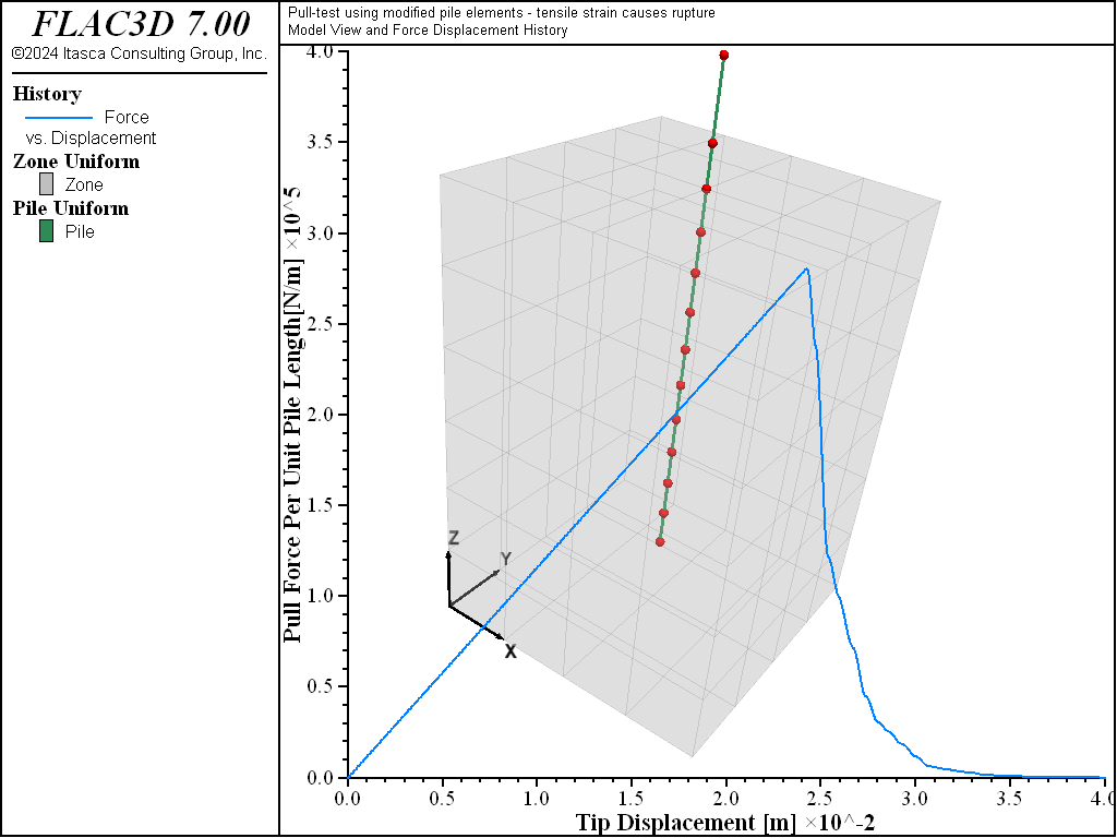
Figure 14: Rockbolt pull force in N/m versus rockbolt axial displacement in meters for the case of a single 25 mm grouted bolt—with tensile rupture.
Shear Test on Rockbolts
This section and the next present two examples of shear tests. The tests are similar to the pull-tests described above, except that a velocity acting on a plane perpendicular to the axial direction of the bolt is applied to the top of the bolt.
The data file “Shear01.dat” shows how the model is created. Note that in the case of a shear test on rockbolts, values of stiffness and strength for the normal coupling springs (that were not needed in the pull-tests) need to be defined. Figure 15 shows a plot of shear force versus shear displacement. We select a stiffness value of 1010 N/m/m and cohesive strength of 108 MPa/m in order to illustrate the shear behavior within a shear displacement range of 6 mm. These values do not represent a specific material and should be adjusted to fit experimental data.
The figure also includes a view of the model after the test. The large displacement of the rockbolt near the rock surface is the result of the yielding of the normal coupling springs, which simulates crushing of the rock.
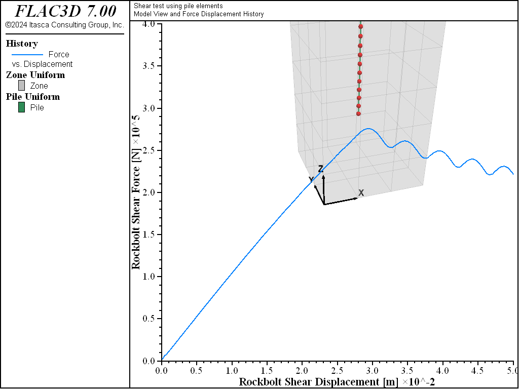
Figure 15: Rockbolt shear force in N versus rockbolt shear displacement in meters for the case of a single 25 mm grouted bolt.
Shear Test on Rockbolts with Rupture
The data file “Shear02.dat” presents a model similar to the one described in Shear Test on Rockbolts, but with the added option of bending rupture. The failure is controlled by specified values of limiting (yield) bending moment and limiting tensile strain (these values are assigned using the keywords plastic-moment and tensile-failure-strain, as described in Pile Commands).
The results obtained with the data file “Shear02.dat” are shown in Figure 16. Note that the relation between applied force and lateral displacement shows some oscillation after rupture. This oscillation is the normal response following the sudden rupture of the bolt.
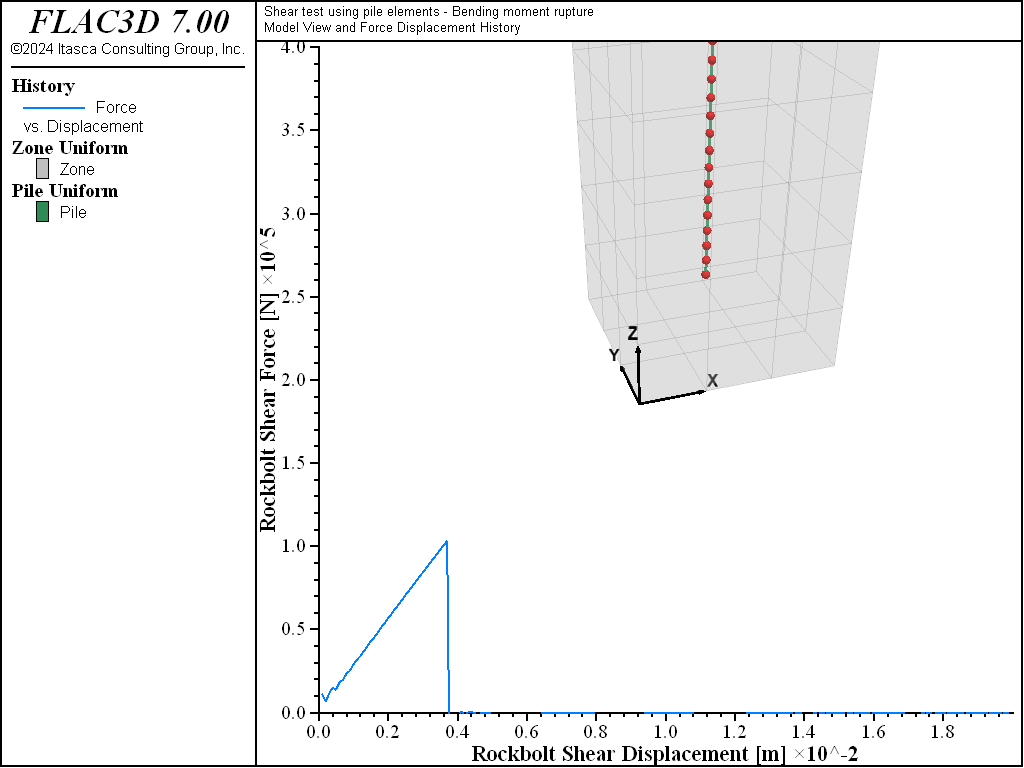
Figure 16: Rockbolt shear force in N versus rockbolt shear displacement in meters for the case of a single 25 mm grouted bolt—with tensile rupture.
References
Hyett, A. J., W. F. Bawden and R. D. Reichert. “The Effect of Rock Mass Confinement on the Bond Strength of Fully Grouted Cable Bolts,” Int. J. Rock Mech. Min. Sci. & Geomech. Abstr., 29(5), 503-524 (1992).
Data Files
Pull01.dat
; ==================================================================
;   Simulation of pull-test for grouted reinforcement
; ==================================================================
model new
model large-strain off
fish automatic-create off
[global t =  'Pull Test for Grouted Cable Anchor ']
[t += '(no external confinement, fric=0)']
model title [t]
; Create a single rock block and set its material properties.
zone create brick size 4 7 4 point 1 (0.4,0,0) point 2 (0,0.7,0) ...
                             point 3 (0,0,0.4)
zone cmodel assign elastic
zone property bulk 5e9 shear 3e9
; Create a single cable and set its associated properties
struct cable create by-line (0.2,0.0,0.2) (0.2,0.5,0.2) segments 10
struct cable property cross-sectional-area 181e-6 young 98.6e9 ...
                      yield-tension 0.232e6 grout-stiffness 1.12e7 ...
                      grout-cohesion 1.75e5 grout-friction 0.0 ...
                      grout-perimeter 7.85e-2
; Fix free end of rock block and apply velocity to cable end
zone face apply velocity-normal 0 range position-y 0
struct node fix velocity-x                    range position-y 0
struct node initialize velocity-x -1e-6 local range position-y 0
; FISH function to calculate reaction force on zones
[global gplist = gp.list(gp.pos.y(::gp.list) < 0.05)]
fish define force
    return list.sum(gp.force.unbal.y(::gplist)) / 0.5
end
; Set up histories for monitoring model behavior
history interval 10
fish history name 'force' force
struct node history name 'disp' displacement-y component-id 1
; Apply velocity to achieve total displacement of 2.0 cm
model cycle 10000
model save 'pull-1-1'
model cycle 6500
model save 'pull-1-2'
model cycle 1000
model save 'pull-1-3'
model cycle 2500
model save 'pull-1-4'
Pull02.dat
; ==================================================================
;   Simulation of pull-test for grouted reinforcement
;     confinement 2 MPa
; ==================================================================
model new
model large-strain off
fish automatic-create off
model title 'Pull Test for Grouted Cable Anchor - Confinement 2 MPa, fric=30'
; Create a single rock block and set its material properties.
zone create brick size 4 7 4 point 1 (0.4,0,0) point 2 (0,0.7,0) ...
                             point 3 (0,0,0.4)
zone cmodel assign elastic
zone property bulk 5e9 shear 3e9
zone initialize stress xx -2e6 zz -2e6
zone face apply stress-normal -2e6 range union position-x 0 ...
                                         position-x 0.4 position-z 0 ...
                                         position-z 0.4
; Create a single cable and set its associated properties
struct cable create by-line (0.2,0.0,0.2) (0.2,0.5,0.2) segments 10
struct cable property cross-sectional-area 181e-6 young 98.6e9 ...
                      yield-tension 0.232e6 grout-stiffness 1.12e7 ...
                      grout-cohesion 1.75e5 grout-friction 30.0 ...
                      grout-perimeter 7.85e-2
; Fix free end of rock block and apply velocity to cable end
zone face apply velocity-normal 0 range position-y 0
struct node fix velocity-x range position-y 0
struct node initialize velocity-x -1e-6 local range position-y 0
; FISH function to calculate reaction force on zones
[global gplist = gp.list(gp.pos.y(::gp.list) < 0.05)]
fish define force
    return list.sum(gp.force.unbal.y(::gplist)) / 0.5
end
; Set up histories for monitoring model behavior
history interval 10
fish history name 'force' force
struct node history name 'disp' displacement-y component-id 1
; Apply velocity to achieve total displacement of 4.525 cm
model cycle 45000
;
model save 'pull-2'
Pull03.dat
; ==================================================================
;   Simulation of pull-test for grouted reinforcement
;     confinement 4 MPa
; ==================================================================
model new
model large-strain off
fish automatic-create off
model title 'Pull Test for Grouted Cable Anchor - Confinement 4 MPa, fric=30'
; Create a single rock block and set its material properties.
zone create brick size 4 7 4 point 1 (0.4,0,0) point 2 (0,0.7,0) ...
                             point 3 (0,0,0.4)
zone cmodel assign elastic
zone property bulk 5e9 shear 3e9
zone initialize stress xx -4e6 zz -4e6
zone face apply stress-normal -4e6 range union position-x 0 position-x 0.4 ...
                                               position-z 0 position-z 0.4
; Create a single cable and set its associated properties
struct cable create by-line (0.2,0.0,0.2) (0.2,0.5,0.2) segments 10
struct cable property cross-sectional-area 181e-6 young 98.6e9 ...
                      yield-tension 0.232e6 grout-stiffness 1.12e7 ...
                      grout-cohesion 1.75e5 grout-friction 30.0 ...
                      grout-perimeter 7.85e-2
; Fix free end of rock block and apply velocity to cable end
zone face apply velocity-normal 0 range position-y 0
struct node fix velocity-x range position-y 0
struct node initialize velocity-x -1e-6 local range position-y 0
; FISH function to calculate reaction force on zones
[global gplist = gp.list(gp.pos.y(::gp.list) < 0.05)]
fish define force
    return list.sum(gp.force.unbal.y(::gplist)) / 0.5
end
; Set up histories for monitoring model behavior
history interval 10
fish history name 'force' force
struct node history name 'disp' displacement-y component-id 1
; Apply velocity to achieve total displacement of 4.525 cm
model cycle 45000
;
model save 'pull-3'
Pull04.dat
; ==================================================================
;   Simulation of pull-test for grouted reinforcement
;   using modified pile elements
; ==================================================================
model new
model large-strain off
fish automatic-create off
model title 'Pull-test using modified pile elements'
; Create a single rock block and set its material properties.
zone create brick size 4 4 6 point 1 (0.4,0,0) point 2 (0,0.4,0) ...
                             point 3 (0,0,0.6)
zone cmodel assign elastic
zone property bulk 5e9 shear 3e9
zone face apply velocity-normal 0.0 range position-z 0.6
; Create a pile element and assign properties
struct pile create by-line (0.2,0.2,0.1) (0.2,0.2,0.7) segments 12
struct pile property rockbolt-flag on
struct pile property young 200e9 poisson 0.25 cross-sectional-area 5e-4 ...
                     perimeter 0.08
struct pile property yield-tension 2.25e5  ; ultimate tensile strength
struct pile property moi-y 2.0e-8 moi-z 2.0e-8 moi-polar 4.0e-8 ; 0.25*pi*r^4
struct pile property coupling-cohesion-shear 1.75e5 ...
                     coupling-stiffness-shear 1.12e7
struct pile property coupling-cohesion-normal 1.75e5 ...
                     coupling-stiffness-normal 1.12e7
; Set up pull out test
struct node fix  velocity-x range position-z 0.7
struct node init velocity-x 1e-6 local range position-z 0.7
; FISH function to calculate reaction force on zones
[global gplist = gp.list(gp.pos.z(::gp.list) > 0.59)]
fish define force
    return list.sum(gp.force.unbal.z(::gplist)) / 0.5
end
; Set up histories for monitoring model behavior
history interval 10
fish history name 'force' force
struct node history name 'disp' displacement-z position (0.2,0.2,0.7)
; Achieve a total displacement of 2.0 cm
model cycle 20000
;
model save 'pull-4'
Pull05.dat
; ==================================================================
;   Simulation of pull-test for grouted reinforcement
;   using modified pile elements - Softening of cohesion
; ==================================================================
model new
model large-strain off
fish automatic-create off
model title 'Pull-test using modified pile elements - cohesion softening'
; Create a single rock block and set its material properties.
zone create brick size 4 4 6 point 1 (0.4,0,0) point 2 (0,0.4,0) ...
                             point 3 (0,0,0.6)
zone cmodel assign elastic
zone property bulk 5e9 shear 3e9
zone face apply velocity-normal 0.0 range position-z 0.6
; Create a pile element and assign properties
struct pile create by-line (0.2,0.2,0.1) (0.2,0.2,0.7) segments 12
struct pile property rockbolt-flag on
struct pile property young 200e9 poisson 0.25 cross-sectional-area 5e-4 ...
                     perimeter 0.08
struct pile property yield-tension   2.25e5  ; ultimate tensile strength
struct pile property moi-y 2.0e-8 moi-z 2.0e-8 moi-polar 4.0e-8 ; 0.25*pi*r^4
struct pile property coupling-cohesion-shear 1.75e5 ...
                     coupling-stiffness-shear 1.12e7
struct pile property coupling-cohesion-normal 1.75e5 ...
                     coupling-stiffness-normal 1.12e7
struct pile property coupling-cohesion-table 'cct'
; change in cohesion with relative shear displacement
table 'cct' add (0,1.75e5) (0.025,1.75e4)
; Set up pull out test
struct node fix velocity-x range position-z 0.7
struct node initialize velocity-x 1e-6 local range position-z 0.7
; FISH function to calculate pile force
[global gplist = gp.list(gp.pos.z(::gp.list) > 0.59)]
fish define force
    return list.sum(gp.force.unbal.z(::gplist)) / 0.5
end
; Set up histories for monitoring model behavior
history interval 10
fish history name 'force' force
struct node history name 'disp' displacement-z position (0.2,0.2,0.7)
; Achieve a total displacement of 4.0 cm
model cycle 40000
;
model save 'pull-5'
Pull06.dat
; ==================================================================
;   Simulation of pull-test for grouted reinforcement
;   using modified pile elements - Confinement 4 MPa
; ==================================================================
model new
fish automatic-create off
[global t =  'Pull-test using modified pile elements - ']
[t += 'Confinement 4 MPa, fric=30']
model title [t]
; Create a single rock block and set its material properties.
zone create brick size 4 4 6 point 1 (0.4,0,0) point 2 (0,0.4,0) ...
                             point 3 (0,0,0.6)
zone cmodel assign elastic
zone property bulk 5e9 shear 3e9
zone face apply velocity-normal 0.0 range position-z 0.6
model large-strain on
; Create a pile element and assign properties
struct pile create by-line (0.2,0.2,0.1) (0.2,0.2,0.7) segments 12
struct pile property rockbolt-flag on
struct pile property young 200e9 poisson 0.25 cross-sectional-area 5e-4 ...
                     perimeter 0.08
struct pile property yield-tension   2.25e5  ; ultimate tensile strength
struct pile property moi-y 2.0e-8 moi-z 2.0e-8 moi-polar 4.0e-8 ; 0.25*pi*r^4
struct pile property coupling-cohesion-shear 1.75e5 ...
                     coupling-stiffness-shear 1.12e7
struct pile property coupling-cohesion-normal 1.75e5 ...
                     coupling-stiffness-normal 1.12e7
struct pile property coupling-friction-shear 30.0
; Install in situ stresses
zone initialize stress xx -4e6 yy -4e6
zone face apply stress-normal -4e6 range union position-x 0 position-x 0.4 ...
                                               position-y 0 position-y 0.4
; Set up pull out test
struct node fix velocity-x range position-z 0.7
struct node init velocity-x 1e-6 local range position-z 0.7
; FISH function to calculate pile force
[global gplist = gp.list(gp.pos.z(::gp.list) > 0.59)]
fish define force
    return list.sum(gp.force.unbal.z(::gplist)) / 0.5
end
; Set up histories for monitoring model behavior
history interval 10
fish history name 'force' force
struct node history name 'disp' displacement-z position (0.2,0.2,0.7)
; Achieve a total displacement of 4.0 cm
model cycle 40000
;
model save 'pull-6'
Pull07.dat
; ==================================================================
;   Simulation of pull-test for grouted reinforcement
;   using modified pile elements - Confinement 4 MPa (w/table)
; ==================================================================
model new
fish automatic-create off
[global t =  'Pull-test using modified pile elements - ']
[t += 'Confinement 4 MPa (w/table)']
model title [t]
; Create a single rock block and set its material properties.
zone create brick size 4 4 6 point 1 (0.4,0,0) point 2 (0,0.4,0) ...
                             point 3 (0,0,0.6)
zone cmodel assign elastic
zone property bulk 5e9 shear 3e9
zone face apply velocity-normal 0.0 range position-z 0.6
model large-strain on
; Create a pile element and assign properties
struct pile create by-line (0.2,0.2,0.1) (0.2,0.2,0.7) segments 12
struct pile property rockbolt-flag on
struct pile property young 200e9 poisson 0.25 cross-sectional-area 5e-4 ...
                     perimeter 0.08
struct pile property yield-tension  2.25e5  ; ultimate tensile strength
struct pile property moi-y 2.0e-8 moi-z 2.0e-8 moi-polar 4.0e-8 ; 0.25*pi*r^4
struct pile property coupling-cohesion-shear 1.75e5 ...
                     coupling-stiffness-shear 1.12e7
struct pile property coupling-cohesion-normal 1.75e5 ...
                     coupling-stiffness-normal 1.12e7
struct pile property coupling-friction-shear 30.0
; define table for confining stress correction factor
table 'cct' add (0,0.5) (0.3,0.48) (0.5,0.45) (0.6,0.39) (0.68,0.36)
struct pile property coupling-confining-table 'cct'
; note : (snn-szz)/(snn+szz) is 1 , so cfac=0.36
; Install in situ stresses
zone initialize stress xx -4e6
zone face apply stress-normal -4e6 range union position-x 0 position-x 0.4
; Set up pull out test
struct node fix velocity-x range position-z 0.7
struct node initialize velocity-x 1e-6 local range position-z 0.7
; FISH function to calculate pile force
[global gplist = gp.list(gp.pos.z(::gp.list) > 0.59)]
fish define force
    return list.sum(gp.force.unbal.z(::gplist)) / 0.5
end
; Set up histories for monitoring model behavior
history interval 10
fish history name 'force' force
struct node history name 'disp' displacement-z position (0.2,0.2,0.7)
; Achieve a total displacement of 4.0 cm
model cycle 40000
;
model save 'pull-7'
Pull08.dat
; ==================================================================
;   Simulation of pull-test for grouted reinforcement
;   using modified pile elements
;     Definition of failure due to maximum tensile strain or stress
; ==================================================================
model new
fish automatic-create off
[global t =  'Pull-test using modified pile elements - ']
[t += 'tensile strain causes rupture']
model title [t]
; Create a single rock block and set its material properties
zone create brick size 4 4 6 point 1 (0.4,0,0) point 2 (0,0.4,0) ...
                             point 3 (0,0,0.6)
zone cmodel assign elastic
zone property bulk 5e9 shear 3e9
zone face apply velocity-normal 0.0 range position-z 0.6
model large-strain on
zone mechanical damping combined
; Create a pile element and assign properties
struct pile create by-line (0.2,0.2,0.1) (0.2,0.2,0.7) segments 12
struct pile property rockbolt-flag on
struct pile property young 200e9 poisson 0.25 cross-sectional-area 5e-4 ...
                     perimeter 0.08
struct pile property moi-y 2.0e-8 moi-z 2.0e-8 moi-polar 4.0e-8 ; 0.25*pi*r^4
struct pile property coupling-cohesion-shear 1.75e5 ...
                     coupling-stiffness-shear 1.12e7
struct pile property coupling-cohesion-normal 1.75e5 ...
                     coupling-stiffness-normal 1.12e7
struct pile property coupling-friction-shear 30.0
struct pile property yield-tension 1.5e5  ; ultimate tensile strength
struct pile property tensile-failure-strain 1.0e-4 ; ultimate tensile strain
; Install in situ stresses
zone initialize stress xx -4e6 yy -4e6
zone face apply stress-normal -4e6 range union position-x 0 position-x 0.4 ...
                                               position-y 0 position-y 0.4
; Set up pull out test
struct node fix velocity-x range position-z 0.7
struct node initialize velocity-x 1e-6 local range position-z 0.7
; FISH function to calculate pile force
[global gplist = gp.list(gp.pos(::gp.list)->z > 0.59)]
fish define force
    return list.sum(gp.force.unbal(::gplist)->z) / 0.5
end
; Set up histories for monitoring model behavior
history interval 10
fish history name 'force' force
struct node history name 'disp' displacement-z position (0.2,0.2,0.7)
; Achieve a total displacement of 2.0 cm
model cycle 40000
;
model save 'pull-8'
Shear01.dat
; ==================================================================
;   Simulation of shear test for a grouted bolt
;   using modified pile elements
; ==================================================================
model new
fish automatic-create off
model title 'Shear test using pile elements'
; Create a single rock block and set its material properties
zone create brick size 3 3 6 point 1 (0.3,0,0) point 2 (0,0.3,0) ...
                             point 3 (0,0,0.6)
zone face skin ; Label the model boundaries
zone cmodel assign elastic
zone property bulk 5e10 shear 3e10 density 2000
zone face apply velocity-normal 0 range group 'Bottom'
zone face apply velocity-normal 0 range group 'East' or 'West'
zone face apply velocity-normal 0 range group 'North' or 'South'
model large-strain on
zone mechanical damping combined
; Create a pile element and assign properties
struct pile create by-line (0.15,0.15,0.1) (0.15,0.15,0.628) segments 22
struct node group 'Top' range position-z 0.628 ; Tag the node at the top
                                               ; with a name
struct pile property rockbolt-flag on
struct pile property young 200e9 poisson 0.25 cross-sectional-area 5e-4 ...
                     perimeter 0.08
; ultimate tensile strength
struct pile property yield-tension   2.25e5
struct pile property moi-y 2.0e-8 moi-z 2.0e-8 moi-polar 4.0e-8
;                         0.25*pi*r^4
struct pile property coupling-cohesion-shear 1.75e5 ...
                     coupling-stiffness-shear 1.12e7
struct pile property coupling-cohesion-normal 1.75e8 ...
                     coupling-stiffness-normal 1.0e9
struct pile property coupling-friction-shear 30.0
; Set up shear test (need to fix local nodal axes at the top node,
; to avoid axes rotating with element)
struct node fix system-local range group 'Top'
struct node initialize velocity-x 1e-6 local range group 'Top'
struct node fix velocity-x range group 'Top'
; FISH function to calculate force on the grid
[global bGroup = gp.isGroup(::gp.list,'Bottom')]
[global wGroup = gp.isGroup(::gp.list,'West')]
[global eGroup = gp.isGroup(::gp.list,'East')]
[global gplist = gp.list(bGroup | wGroup | eGroup)]
fish define force
    return list.sum(gp.force.unbal.x(::gplist))
end
; Set up histories for monitoring model behavior
history interval 100
fish history name 'force' force
struct node history name 'disp' displacement-x position (0.15,0.15,0.628)
; Achieve a total displacement of 5.0 cm
model cycle 50000
;
model save 'shear-1'
Shear02.dat
; ==================================================================
;   Simulation of shear test for a grouted bolt
;   using modified pile elements - Bending moment rupture
; ==================================================================
model new
fish automatic-create off
model title 'Shear test using pile elements - Bending moment rupture'
; Create a single rock block and set its material properties
zone create brick size 3 3 6 point 1 (0.3,0,0) point 2 (0,0.3,0) ...
                             point 3 (0,0,0.6)
zone face skin ; Label the model boundaries
zone cmodel assign elastic
zone property bulk 5e10 shear 3e10 density 2000
zone face apply velocity-normal 0 range group 'Bottom'
zone face apply velocity-normal 0 range group 'East' or 'West'
zone face apply velocity-normal 0 range group 'North' or 'South'
model large-strain on
zone mechanical damping combined
; Create a pile element and assign properties
struct pile create by-line (0.15,0.15,0.1) (0.15,0.15,0.628) segments 22
struct node group 'Top' range position-z 0.628 ; Tag the node at the top
                                               ; with a name
struct pile property rockbolt-flag on
struct pile property young 200e9 poisson 0.25 cross-sectional-area 5e-4 ...
                     perimeter 0.08
; ultimate tensile strength
struct pile property yield-tension   2.25e5
; ultimate moment and tensile strength
struct pile property plastic-moment   5e3 tensile-failure-strain   1e-4
struct pile property moi-y 2.0e-8 moi-z 2.0e-8 moi-polar 4.0e-8
;                        0.25*pi*r^4
struct pile property coupling-cohesion-shear 1.75e5 ...
                     coupling-stiffness-shear 1.12e7
struct pile property coupling-cohesion-normal 1.75e8 ...
                     coupling-stiffness-normal 1.0e10
struct pile property coupling-friction-shear 30.0
; Set up shear test (need to fix local nodal axes at the top node,
; to avoid axes rotating with element)
struct node fix system-local range group 'Top'
struct node initialize velocity-x 1e-6 local range group 'Top'
struct node fix velocity-x range group 'Top'
; FISH function to calculate force on the grid
[global bGroup = gp.isGroup(::gp.list,'Bottom')]
[global wGroup = gp.isGroup(::gp.list,'West')]
[global eGroup = gp.isGroup(::gp.list,'East')]
[global gplist = gp.list(bGroup | wGroup | eGroup)]
fish define force
    return list.sum(gp.force.unbal.x(::gplist))
end
; Set up histories for monitoring model behavior
history interval 100
fish history name 'force' force
struct node history name 'disp' displacement-x position (0.15,0.15,0.628)
; Achieve a total displacement of 2.0 cm
program warning off
model cycle 20000
program warning on
;
model save 'shear-2'
Endnotes
| [1] | To view this project in FLAC3D, use the program menu.
⮡ FLAC |
| [2] | This effect is explored in some detail in Hyett et al. (1992). |
| Was this helpful? ... | 3DEC © 2019, Itasca | Updated: Feb 25, 2024 |