Adding Blocks
When you create a new set of building blocks, it starts out with one block. You can add more blocks to that block by means of the Add Blocks tool ( ) in the toolbar. An alternative is to create a free-standing block by way of a command in the context menu. You can also add more than one block at a time by using the tool button labeled “Add a Layer…” (
 ) which lets you add a flat layer or a layer that rotates around an axis.
Using the Add Blocks Tool
When you click the Add Blocks tool, it puts the mouse into a mode where you can add one block after another.
Start by clicking a face that you want to add a block to. The green outline of a block appears. Click the same face again and the block will be added to the face.
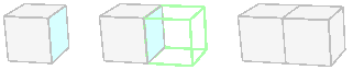
In most cases, you will have a choice of more than one kind of block to add. When you click a face, the mouse cursor changes to show the outline of a block with two arrows ( ). The arrows indicate whether another option exists for the shape of the block.
Mouse Cursor |
Description |
|---|---|
|
Scrolling up or down will show a different shape. |
|
Scrolling down will show a different shape. |
|
Scrolling up will show a different shape. |
|
There are no other shapes available to add. |


You can use arrow keys or the mouse wheel to scroll through the available shapes. When using the mouse wheel, the pointer must be over the face that was clicked, otherwise the whole view will zoom in or out. Pressing the Return or Enter key is another way to accept the proposed shape.
If you make a mistake and add the wrong kind of block, you can right-click the block and choose Delete Block from the context menu. Or use the Edit>Undo command to remove the mistake from the record.
While the list of shapes is displayed, pressing the ESC key will cancel the operation. Pressing ESC again will take the mouse out of Add Blocks mode.
Green outlines represent good (valid) blocks and red outlines represent blocks that will create invalid geometry if added to the model. You can add an invalid block but the geometry will need to be repaired before zones can be generated.
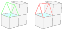
The block to be added may have faces that are attached or unattached to adjacent faces. A colored adjacent face (red or green) shows that the face will be attached to the new block; a gray face will not be attached.
To help determine which faces in a model are attached, there is a “Show Surfaces” command in the Validate menu.
Note: If you find that clicking a face with the Add Blocks tool does not show a list of blocks, the face may have one of its blocks hidden. In that case, the context menu for that face will have a command to show the hidden block. The mouse cursor should also change to indicate when a hidden block will prevent a block from being added to a face( ).
).
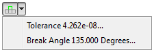
Settings
The arrow at the right side of the Add Blocks tool button shows a menu that lets you set tolerance and the break angle.
Tolerance
The tolerance setting determines how close together two points need to be before they are considered to be at the same location. It also determines how close a point can be to any object before it is considered to intersect that object.
- A recommended value is computed and updated as the model changes. You may want to override that value for a couple of reasons:
If you add a new block when the tolerance setting is too small, new points in that block may not automatically merge with pre-existing points as they should.
If the tolerance is too large, blocks may get marked as bad (red), due to intersections, when they shouldn’t. The tolerance can be so large that points appear to intersect other objects. This problem usually arises in models that are relatively large compared to the levels of small detail that occur within them. Setting the tolerance to a smaller value may help resolve the bad blocks. After setting the tolerance, use the Validate command in the Validate tool menu (
 ) to see if the new value has an effect.
A checkbox determines whether the recommended tolerance will continually be used.
View Tolerance: The status bar contains a “View Tolerance” number that is based on the current zoom level of the Building Blocks pane and the size of the points. It is a low-precision estimate of the radius of the points. You may want to use this number as a tolerance setting if you have problems adding (or splitting) a block.
Break Angle
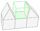
The break angle determines how wide an angle to consider when proposing new blocks.
A break angle of 110 degrees will not allow a block that fills the valley displayed in the picture. A break angle of 135 degrees will.
Adding a Free Block
When you want to add a block that is not attached to any other block, you can use the command “Add a Free Block” from the context menu when the mouse is in Selection mode (![]() ).
).
The following dialog will be displayed:

You may specify the shape of the block and the length of the edges. You may place the center of the block at the center of the view or provide x, y and z coordinates.
This dialog will also appear when there are no blocks in the set and you left-click inside the pane.
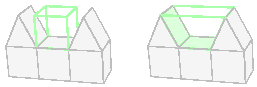
Adding a Layer
To add a layer of blocks, first select the faces where the layer should be added. The next step depends on whether you want to rotate the new layer around an axis (for axial symmetry).
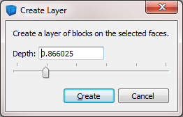
If you want to add a flat layer, just click the tool button labeled “Add a layer…” (). A dialog will appear to let you adjust the depth of the new layer. You can enter a precise numeric value or use the horizontal slider. You also have the option of reproducing the shape of the starting face(s) in the extruded face(s) with the use of the “Keep shape” check box. Click the Create button to add the layer.
To create axial symmetry, you’ll need to move the handle out of the range of the current selection before you click the “Add a layer…” button. There are several ways to do this. One is to hold down the Alt key while dragging an axis arrow to a new location. Another way is to right-click the reference point on the handle to show the context menu, and then choose the “Relocate Handle To…” command. The handle’s reference point will serve as the center of rotation for the new blocks. Once the handle is relocated, click the “Add a layer…” () tool button.
When you move the handle away from the selection or to the edge of the selection along any axis, the Angle option will be enabled in the dialog.
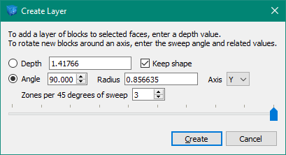
You can curve blocks through a maximum of 90 degrees at a time. If you do more than 45 degrees, each block will be split to lessen the chance of there being a bad dihedral angle in the result.
The radius can be edited within a range of positive values.
The axis control will have one or two options available depending on the position of the handle in relation to the selection. It never allows rotation around the axis closest to the normal vector of the selection.
You can specify in advance the number of zones per 45 degrees of sweep angle. Zone density can also be adjusted after the blocks have been created.
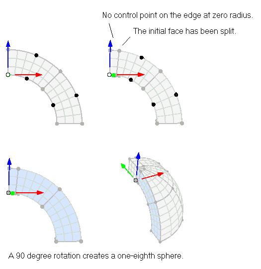
The shapes of rotated edges (with the use of control points) will be maintained through the sweep, with an exception for edges at zero radius. Face control points are not maintained.

Limitations at Zero Radius
There are limitations on the faces that may be rotated when the radius is zero.
A quad or triangular face must have one edge at zero radius. A single point at zero radius is not allowed.
Multiple edges are allowed at zero radius, but they must be contiguous.
An edge at zero radius is not allowed to have a control point.
An edge radiating from zero radius (only one end point at zero radius) is not allowed to have a control point.
A triangular face at zero radius must have its degenerate corner at zero radius.
If you need to rotate an edge with control points at zero radius, consider splitting the edge to make a small edge at zero radius whose length matches the zone size you need. Then remove the control points from the short edge and adjust the zone density of the two edges. Then do the rotation.
The example below shows two faces forming an arc, where one face gets split to produce an edge whose control points can be removed. Then the selected faces can be rotated 90 degrees to create an eighth of a sphere.
| Was this helpful? ... | Itasca Software © 2024, Itasca | Updated: Nov 12, 2025 |
