Object Properties
Setting Object Properties
All objects in a sketch set have properties that may be edited, which is done by selecting the object(s) of interest and accessing the desired properties as follows:
Using the Tools Area
Enter the property value(s) desired in the appropriate fields in the Tools Area.
Using the Popup Property Editor
Press one of: spacebar | Ctrl + ← | Ctrl + → or
Right-click: select “Edit [Object] Properties” from the menu.Toggle the properties[1] by pressing: Ctrl + ← | Ctrl + → or click the corner arrow buttons until the desired property is showing.
Note
When multiple objects are selected, only properties that may sensibly be applied to all object members of the selection are available for editing; other properties are disabled.
The properties available in the Tools Area and on the Popup Property Editor are in almost all cases identical—meaning the choice of which to use is a matter of personal preference. (One exception is that the Popup Property Editor is not available for imported images.)
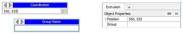
Figure 1: Editing the properties of a sketch point: panels from the Popup Property Editor on the left, the “Object Properties” panel in the Tools Area on the right.
Objects with Editable Properties
In the front view, points, edges, control points, blocks, images and geometric data sets have editable properties. In the section views (side, top, bottom), the starting point, points, edges, and the extrusion axis have editable properties.
The editable properties of each object type are described below. Points and edges are only presented once, as they are handled identically in the front and section views.
Points
Figure 2: The popup property editor and control panel for a single point
Coordinates/Position: This is the x and y position of the point. This may be specified with numbers or with FISH variables (note that a single FISH variable can contain a vector and thus be a valid entry for the point position).
Group: One or more points may be grouped together by assigning them to a named group. See the topic Groups for more information.
Note the extrusion starting point, visible in a section view, is a special case, and is described below.
Edges
Figure 3: The popup property editor and control panel for a selected edge
Edge Type: Specifies one of three types of edge: line, curve, arc. See the topic Curved Edges for information on working with each.
Zones: Specifies the number of zones along an edge. This will override any automatic zoning that has previously been applied to the block that contains the edge.
Ratio: Ratio can be edited when a single edge is selected. It specifies the zoning ratio to use along the edge, where the base setting is 1 (no ratio). Though values may validly range from zero to infinity, most cases should reasonably fall between to .5 to 2.
Group: One or more edges may be grouped together by assigning them to a named group. See the topic Groups for more information.
Blocks
Figure 4: The popup property editor and control panel for blocks
Zone Multiplier: The number of zones specified along the edges of a block will be multiplied by the integer value provided here. See the topic Zoning for more information on methods to control the zoning in a block.
Group: One or more blocks may be grouped together by assigning them to a named group.
Background Images: Bitmap Images
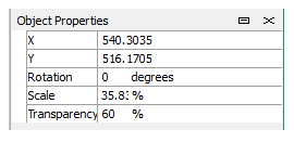
Figure 5: The control panel for images
X and Y: These are the coordinates of the top-left corner of the selected image.
Rotation: This specifies the angle of rotation around the top-left corner of the image. When using the mouse to rotate the image, it will rotate around its center.
Scale: This is a percentage of the original size that the image is scaled to. The image will be scaled using the top-left corner as a reference point.
Transparency: A percentage saying how transparent the image is.
Background Images: Geometric Data
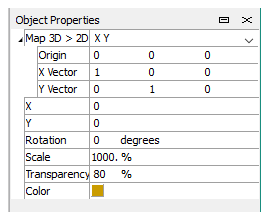
Figure 6: The control panel for imported geometric data
Geometric data can be an imported DXF file, an STL file, or one of Itasca’s .GEOM files.
Map 3D > 2D: When a file of 3D data is imported, you can change its origin and orientation in the display using the controls here.
X and Y: The position of the geometry relative to its origin.
Rotation: Rotation around the center of the geometric data.
Scale: Scale relative to the origin of the geometry.
Transparency: A percentage saying how transparent the data is.
Color: You can change the color used to represent the geometric data by clicking the color control.
Extrusion Starting Point
The starting point (the leftmost point in a sketch, rendered red), can have its Position and Group edited using the techniques described above. However, the starting point must be unlocked to do so. By default the point is locked. To unlock, select the point, right click, and choose “Unlock First Node” from the menu (repeat process to re-lock the point as needed).
Extrusion Origin & Orientation
The axis control that appears in the section views (side, top, and bottom) is used to provide location and orientation properties for extrusion. These operations are described in the Extrusion Orientation section of the Extrusion topic.
Endnote
| Was this helpful? ... | Itasca Software © 2024, Itasca | Updated: Nov 12, 2025 |
