Extrusion (3D only)
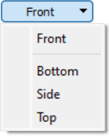
In FLAC3D, the extrusion of the sketch set is visualized by choosing any section view (side, top, bottom) from the view selector on the toolbar (see adjacent image). These views are used to determine the extent, shape, and zoning of extrusion in the third (extruded) dimension.
Basic operations involve defining the length of extrusion, using points to extend and shape the path in any section, using control points to shape or curve path edges, and specifying zoning along each edge of the path.
Advanced operations include specifying a relative path, and shifting the orientation of the model in 3D space.
Selection & Properties
Selection in section views occurs as described in Object Selection. Similarly, setting and changing properties on points, control points, edges, and the origin in the section views is described for all sketch objects in Object Properties.
Initial Extrusion
A first viewing of a sketch in a section view (side, top, or bottom) will show an automatically calculated extent of extrusion and initial zoning — assuming there is at least one meshed block in the front view (the calculation is based on extent of mesh in the front view, and cannot be performed when no mesh is present).
The section views present a view plane perpendicular to the viewing plane of the front view. The extent in the direction of extrusion is indicated as starting at the red square point at the left and moving horizontally to the white square point at the right. The red segment at the left (front) of the extrusion indicates the extent of the sketch along the front plane as seen from the current section view.
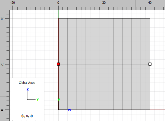
Figure 1: The “side” view showing an initial extent of extrusion.
Initial Extrusion Path
The path of extrusion, from the first node (red) to the end, behaves like an edge in the front view: it is composed of points, edges between points along which zoning is specified, and, optionally, control points that may be used to add curvature to edges. Operations on the path follow the same procedures and are performed using the same tools as described in the topic Points and Edges.
Defining the Extrusion Path
As described above, initially a sketch seen in a section view will have one linear, horizontal, auto-calculated, and auto-zoned extent. The left end point is red, and cannot be deleted. The right end is a normal point that may be moved or added to using the same techniques and tools as used for edges in the front view (see Create, Add to, or Split Edges). Similarly, points or edges that define the path may be deleted with the same techniques used in the “front” view.
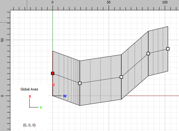
Figure 2: Extension using the Line tool allows definition of a nonlinear extrusion path.
By default, the starting point is locked and its position cannot be changed. Unlocking this point is described below.
Curving the Extrusion Path
Curvature is added to the extrusion path with control points which, again, will behave on the path exactly as on edges in the *front* view. The effect of control points varies based on the edge type property setting (line, curve, arc) of the edge to which they are applied.
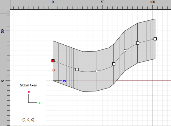
Figure 3: Control points added to edges allow for introduction of curvature to the path.
Meshing Along the Extrusion Path
Each edge of the extrusion path has the same zoning properties as an edge in the front view. In the last three images above, a ratio (0.8) has been applied to the first extrusion edge that lies between the starting point and the next node. As with edge zoning in the front view, be aware that use of the automatic zoning tool will override the zoning that has been created along individual edges of the path. Zoning along a path edge may be set or edited in any section view.
Building the Sketch
When meshed blocks are constructed in the front and section views, the Create Zones tool (  ) and the Create building blocks … (
  ) tool are available on the toolbar in any section view. See the topic Generating Zones for more information.
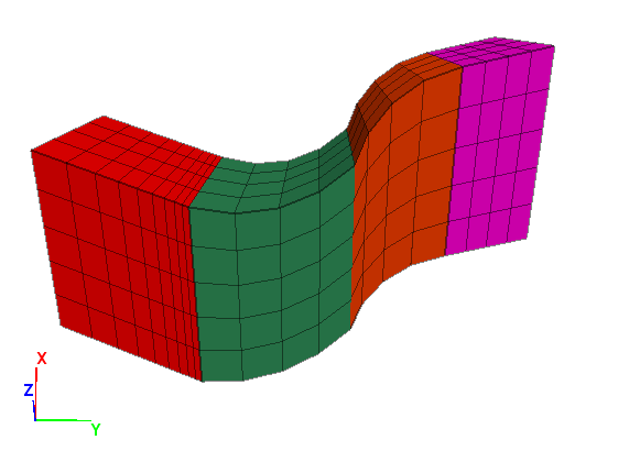
Figure 4: Using the Create Zones tool ( ) issues the commands necessary to construct zones from the finished set.
Advanced Topics
Relative Extrusion Path
The starting point may be unlocked by first selecting it, then right clicking it, then choosing “Unlock First Node” from the context menu. Once unlocked, the point may be manipulated as any normal point (though, note, never deleted).
When the starting point is moved off the visible extrusion, the path is still applied to the extrusion, though now it is relativized. A path that has been moved off the extrusion in this way may be returned to a centered position on the extrusion by selecting the starting point, then right clicking it, then choosing “Centralize Path” from the context menu. Use of a relativized path is not necessary while working interactively in sketch. A relativized may result in cases where users are creating paths from commands, in which case it may be easier to specify the path along relative coordinates rather than in model coordinates.
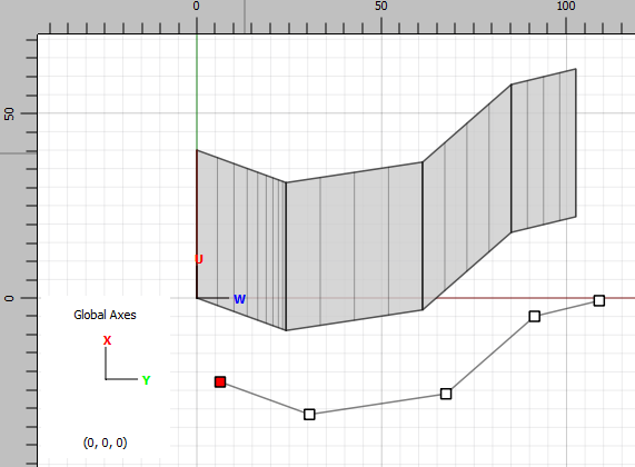
Figure 5: A “relativized” path will provide the same definition of extrusion length and segmentation as one attached to the rendered extrusion shape.
Extrusion Orientation
Figure 6: The axis control. The blue highlight indicates the control has been selected. The current position of the origin is indicated at the bottom of the control.
By default, a sketch has an origin at 0,0,0 in model coordinates, and will extrude along the \(y\)-axis in the positive direction. These settings can be changed. To do so, select the sketch axis control by clicking it with the select tool (  ). The control is available in any section view (side, top, or bottom) but does not appear in the front view. The orientation and position of the sketch may be set using normal property-editing methods.
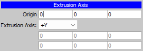
Figure 7: The axis control properties, currently set to sketch defaults.
The origin is moved by entering new \(x\)-, \(y\)-, or \(z\)-coordinate(s), respectively, on the “Origin” line. Extrusion orientation in model space is set using the “Extrusion Axis” selector, which offers the direction options: positive/negative \(x\), \(y\), or \(z\), or the option “Extrude, X”. With one of these selected, the position of the origin and the selected direction are sufficient to orient the extrusion. The “Extrude, X” option facilitates setting the extrusion orientation in any direction.
When “Extrude, X” is selected, two additional fields appear: “Extrude” and “X”. The first defines a unit vector that articulates the direction of extrusion. The second is used to provide 3D orientation by defining a plane that is formed by itself and the “Extrude” unit vector. With these two defined, an “Extrude, Y” unit vector that is perpendicular to the “Extrude, X” plane is implied; with it an “Extrude Plane X-Extrude Plane Y” plane is defined by FLAC3D. The model is now oriented so that this plane is coincident with the plane on which the construction view sits (the front view showing the “face” of the sketch). Finally, when a mesh is generated the extrusion direction will be perpendicular to the “Extrude Plane X-Extrude Plane Y” plane, even though the initially supplied “Extrude” unit vector may not be. This adjustment is made automatically when the extrusion is performed.
| Was this helpful? ... | Itasca Software © 2024, Itasca | Updated: Nov 12, 2025 |
