Workspace Features
Undoing Operations
Actions in the sketch workspace are undone using the “Undo” command available on the Edit Menu or by the keystroke command ctrl + Z.
The “Undo” command will undo the last FLAC command(s) issued by the interface. All user interface actions affecting the model are “transcribed” into FLAC commands. Using “Undo” actually returns to the point of the last project save, project restore, or project new command and reruns all commands that have been issued, up to the last one — the one that is the target of the undo command. There are cases where a single “Undo” will “erase” more than one line from the command record. Conversely, because some single actions in the user interface require two (or more, even) FLAC commands to complete, “Undo” may have to be used twice (or more) to erase the last user interface action. Note that “Undo” is not limited to commands issued in the Extrusion pane; however, if successive uses cause it to “backtrack” to operations performed in other panes (the Console pane, for instance), it will not change the currently active pane when it does so.
When an Undo command will take longer than 15 seconds (by default), a warning dialog will appear and provide the option to cancel the operation. The default limit may be changed/set by providing a new value in the “Undo Warning Limit (seconds)” field in the “General” panel of the Options dialog.
There are limitations to the application of the undo command. For complete information on the use of the command, its limitations and other considerations, see cmd:\(program.undo\) for further information.
esc Key
Mouse operations may be canceled midstream by pressing the esc key. If in mid-drag of an object, the esc key will cancel the move operation. After pressing, the mouse is put into Select mode ( ![]() ).
).
View Manipulation
Because the information presented in front and section views of the sketch workspace is two-dimensional, the workspace subsets the complete view manipulation tools found in FLAC3D. View manipulation is performed via the mouse directly in the workspace, or with controls in the Tools area.
Key + Mouse Commands Reference
ctrl + R : reset the view
right mouse + click-and-drag (Select mode (
 active) : pan
right mouse + Shift + click-and-drag (tools active)* : pan
mouse wheel : zoom in (roll up) or out (roll down)
ctrl+alt+L : zoom to the current selection
*Due to right-click selection overload of point, line, and block tools, panning when any of those tools are active requires holding the shift key while right-click-and-dragging the view.
View Controls in the Tools Area
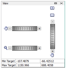
Figure 1: View controls as they appear in the Tools Area of the sketch workspace.
The control set provides the following controls: dials for vertical and horizontal panning ( ), a dial for increasing/decreasing magnification (
 ), a reset view button (
 ), and a zoom to selection button (
 ). In addition, the lower part of the control set reports “Min Target” and “Max Target.” The first sets the left and bottom positions of the model view extent, respectively; the latter sets the right and top positions of the model view extent, respectively (all in model coordinates). The values indicated are editable; a new value entered into one of these areas will be applied as soon as any action is taken to remove focus from the edit field.
Using FISH
FISH input (symbols or inline functions) can be supplied to specify the position of a point or a control point in an extrusion set, as described in Creating Points and Edges.
When FISH symbols or inline functions are provided for values this way, it is critical to remember that the FISH input is only evaluated after it has been entered. As a result, there are a range of possible outcomes that it is useful to understand and anticipate. If a symbol or inline function evaluates to a usable value, then that value is used and all proceeds normally. If a symbol for a variable that has not been initialized is supplied, a dialog will appear asking you to supply a valid initial value for the symbol. If a symbol for a variable evaluates to an unacceptable value, an error results. If an inline function evaluates to an unacceptable value, an error also results.
When using a symbol for a function, there are additional considerations. The supplied symbol will produce an error if the function returns an unacceptable value. It will also produce an error if the function’s arguments are not also supplied when the symbol is given. Lastly, and critically, whatever actions the function performs prior to returning a value will occur, regardless of whether the return value produces an error or not. It is up to the user to know the contents of the function, how it will affect the model, and the nature of its return value. FLAC has no way to validate or error check in advance to prevent unintended effects when the function is supplied.
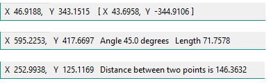
The Status Bar
The program status bar shows information related to the sketch workspace. It reports the model coordinates of the mouse position and, when dragging a point with the mouse, the position of the point (in brackets [ ]).
While adding a new edge, the angle from the horizontal axis and length of the edge are shown.
When 2 points are selected or an edge is selected, the distance between the two points will be displayed.
| Was this helpful? ... | Itasca Software © 2024, Itasca | Updated: Nov 12, 2025 |
