FLAC3D Theory and Background • Zone Joints
Creation of Zone Joint Geometry
Zone joints are created with the zone joint create command. Zones must first be separated, unless separate sub-grids exist that do not share gridpoints and faces. Zone joints can only be created between separated faces and gridpoints, not in the middle of contiguous zones.
The simplest, and intended, pathway to creating zone joints is to group all zone faces in the same slot with different group names. Then the zone joint create by-slot command will create all zone joints at once. Instead of separating zone faces in a separate step, it is recommended that the separate keyword be given as well, ensuring that attaches are cleared when separating the zone faces.
If zone separation is done in a separate step (not the recommended pathway), care must be taken to ensure that zone separation has completed successfully before creating zone joints. For instance, attaches present along faces to be separated will, by default, result in an incomplete separation. Zone joints may not exist in this circumstance as they require the absence of non-manifold conditions. One must use the clear-attach keyword when separating zone faces to avoid any potential issues if attaches are already present. If the zone attach command is given after zone joints are created, on the other hand, attaches will not be created along the faces with zone joints.
Unlike interfaces, zone joints are two-sided. They are made by first creating walls on the opposing faces. Contacts then form automatically between the walls. So, the procedure for creating zone joints is similar to creating interfaces, with the following extra considerations:
Before creating zone joints, you need to issue the command
zone joint configure. This sets up the required data structures for zone joints, turns the model to small strain (large strain is not currently supported with zone joints), and sets the default contact model to the Mohr model.Before creating zone joints you need to separate all of the faces. This is different from interfaces where the separation and interface creation can be done simultaneously. Since zone joints are two-sided, this approach will not work since all of the intersections need to be resolved before creating the zone joints.
Faces on both sides of the separation must be identified. The easiest ways to do this are to group the internal faces before separation, or skin the model after separation (
zone skin). Note that meshes imported from Griddle already have group names assigned to the internal faces.
A simple example illustrating the procedure for zone joint creation is provided here, in 2D and 3D. The example is a block specimen containing a single joint dipping at an angle of 45°.
DippingJoint.dat
model new

zone create brick size 3 3 3 ...
        point 0 (0,0,0) point 1 (3,0,0) point 2 (0,3,0) point 3 (0,0,1.5) ...
        point 4 (3,3,0) point 5 (0,3,1.5) point 6 (3,0,4.5) point 7 (3,3,4.5) ...
        group 'Base'
zone create brick size 3 3 3 ...
        point 0 (0,0,1.5) point 1 (3,0,4.5) point 2 (0,3,1.5) point 3 (0,0,6) ...
        point 4 (3,3,4.5) point 5 (0,3,6) point 6 (3,0,6) point 7 (3,3,6) ...
        group 'Top'

; Create zone joints

; first assign group name to faces to be separated
zone face group 'Joint' internal range group 'Top' group 'Base'

; now separate
zone separate by-face range group 'Joint'

; now create zone joints
zone joint configure
zone joint create by-face range group 'Joint'
Figure 1 shows the zones. Two sub-grid groups are defined: a Base grid and a Top grid. Figure 2 shows the model with the zone joints between the zones.
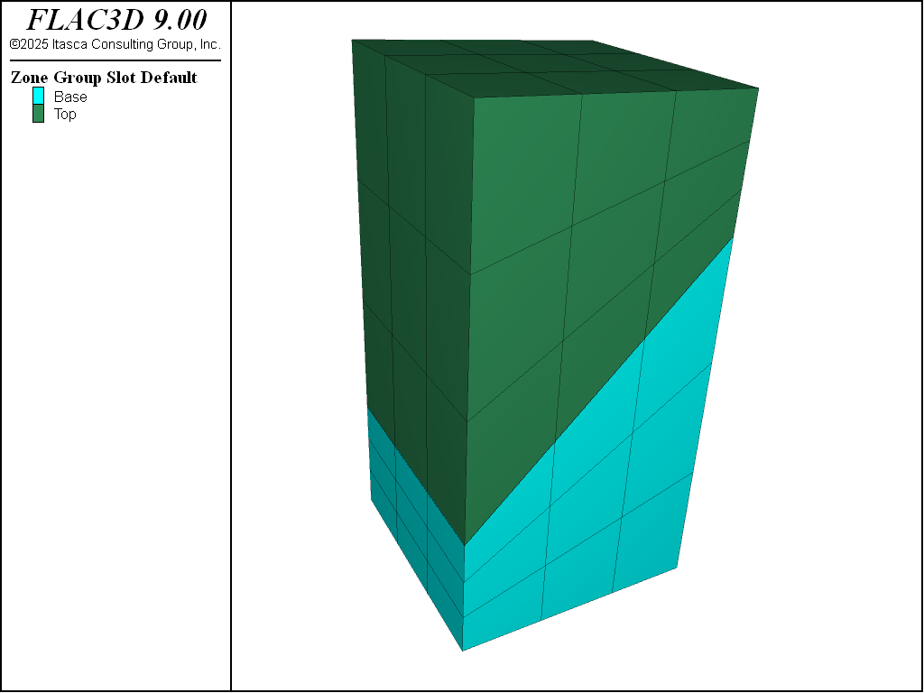
Figure 1: Initial geometry before creation of the zone joint.
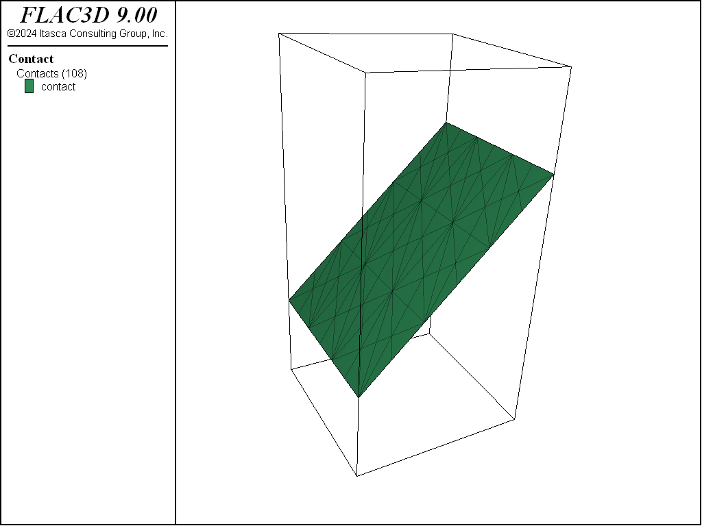
Figure 2: Zone Joint.
| Was this helpful? ... | Itasca Software © 2024, Itasca | Updated: Nov 12, 2025 |
