Undrained Embankment Loading (FLAC2D)
Problem Statement
A common type of analysis in civil engineering practice is estimation of pore pressure development in saturated foundation soils when loaded by an embankment under undrained conditions. The conventional approach to determine the excess pore pressure is to use the expression proposed by Skempton (1954):
where A and B are the pore-pressure coefficients, and \(\Delta \sigma_1\) and \(\Delta \sigma_3\) are the total principal stress increments due to the embankment loading. If it is assumed that the groundwater is incompressible (which is commonly done in practice) and that the soil mass behaves as an isotropic and elastic material, then (1) reduces to
We use this simple expression to illustrate the application of FLAC2D to calculate excess pore pressure resulting from an undrained embankment loading.
This FLAC2D exercise is a derivation of a simple embankment loading example provided by Lambe and Whitman (1969) (see Figure 26.14). In this example, a heavy soil embankment is placed over a foundation clay. It is assumed that the loading is applied more rapidly than drainage can occur, so that undrained conditions apply. The embankment is in the shape of a truncated cone; the embankment configuration and dimensions and the location of the water surface are shown in Figure 1. The excess pore pressure is monitored at an elevation of −31.5 ft, directly beneath the center of the embankment.
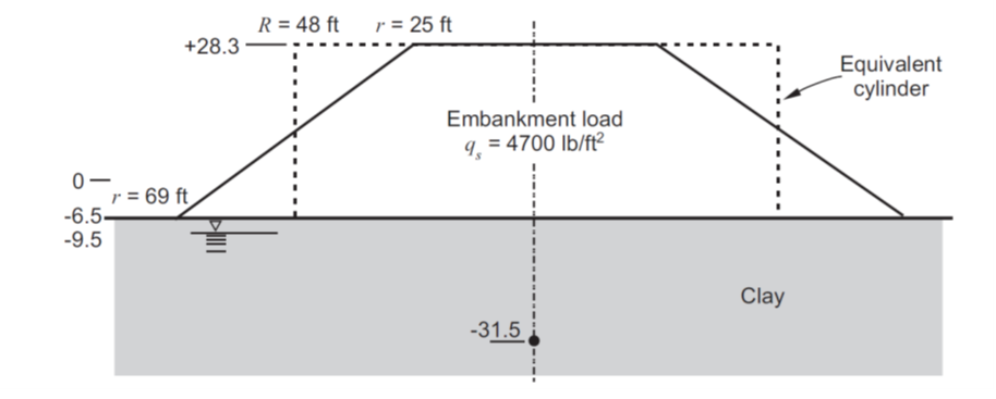
Figure 1: Embankment on clay foundation (from Lambe and Whitman 1969, Figure 26.14).
The clay foundation material is assumed to have an unsaturated unit weight of 93.8 pcf. For comparison of (2) to the FLAC2D solution in this exercise, we assume that the clay behaves as an elastic material. The drained elastic modulus of the clay is 145,000 psf, and the drained Poisson’s ratio is 0.45. The porosity of the clay is 30%.
In the Lambe and Whitman example, the embankment loading is approximated by a vertical pressure of 4700 psf applied at the ground surface over a circular area with a 48 ft radius. Based on this form of loading, the total principal stress increments at a depth of −31.5 ft beneath the center of the circular area are \(\Delta \sigma_1 = 4180 psf\), and \(\Delta \sigma_3 = 1645 psf\) (determined from the stress distribution charts for a uniform load on a circular area; see Figure 8.5 in Lambe and Whitman 1969). The excess pore pressure (from (2)) is then \(\Delta u = 2490 psf\).
FLAC2D Model
The FLAC2D simulation of this problem is performed in axisymmetry mode with the groundwater flow configuration. The groundwater-flow calculation is turned off; excess pore pressure generation is controlled by specifying the water bulk modulus.
The model grid is created to provide finer zoning beneath the region of the applied embankment loading. The zoning is done to position a row of zones with centroids at −31.5 ft, for comparison to the Lambe and Whitman solution. The model grid is shown in Figure 2:
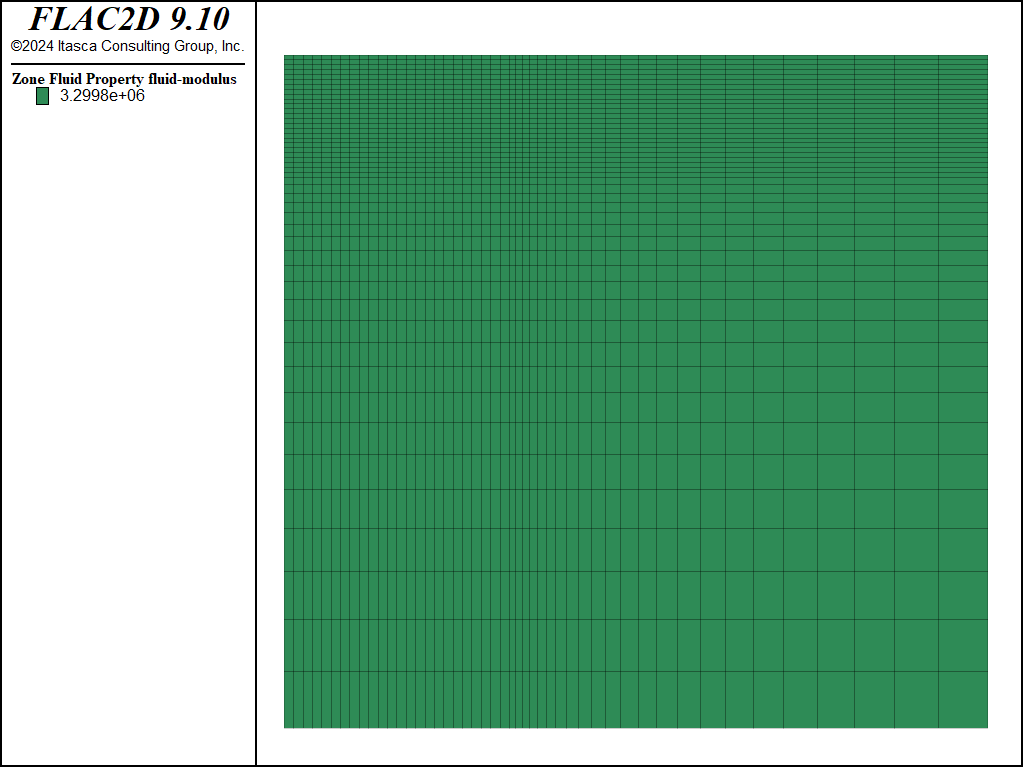
Figure 2: FLAC2D grid for undrained embankment loading problem.
We first set the water bulk modulus to zero (the default) and calculate the initial stress state with the k0 values equal to 0.637. The values for the ratios of effective horizontal stress to effective vertical stress, are selected to produce a total horizontal stress to total vertical stress ratio of 0.818. This ratio corresponds to the stress state computed for gravitational loading of an isotropic elastic material with a Poisson’s ratio of 0.45, which is the assumed initial condition for the Lambe and Whitman problem.
Next, the embankment loading is simulated by applying a vertical pressure of 4700 psf at the ground pressure. The loading is applied gradually in order to produce a monotonic increase in pressure in the soil foundation. This type of loading is not required in this case because the foundation material is assumed to be elastic. However, if a plastic material model is assigned to the foundation, then loading should be gradual to minimize any effects of transient forces that may arise from the loading.
For the loading phase, the water bulk modulus must be specified in order to generate pore pressures as a result of the applied loading. The assumption of incompressible groundwater, in (2), is approximated in the FLAC2D model by selecting a water bulk modulus, \(K_w\), equal to
where \(n\) is the porosity, and \(K\) and \(G\) are the bulk and shear moduli of the unsaturated soil. This calculation is performed automatically and the fluid modulus is set with the command zone fluid modulus-automatic. In this model the calculated \(K_w\) is 3,300,000 psf.
By default, changes mechanical changes (i.e. volumetric strain) *do not* cause pore pressure changes in the model. To simulate this undrained effect, you must explicitly turn on this capability with the command zone fluid property pore-pressure-generation on.
A FISH function, pphist_ini, stores the initial values for total stress and pore pressure before loading, and another function, pphist, monitors the change in total stress and pore pressure resulting from the applied load. These FISH variables are then recorded as histories for comparison to the Lambe and Whitman values.
Results and Discussion
The comparison of the FLAC2D solution to the Lambe and Whitman solution for the total principal stress change due to the embankment loading is illustrated in Figure 3. The final FLAC2D value for :math:Delta sigma_1 is within 0.52% of the Lambe and Whitman solution, and the value for \(\Delta \sigma_3\) is within 2.5%.
The comparison of excess pore pressure is shown in Figure 4. The FLAC2D value is within 3.5% of the Lambe and Whitman value. Note that the difference between the values can be reduced by increasing the water bulk modulus. However, this will also increase the calculational stepping required to reach the equilibrium solution.
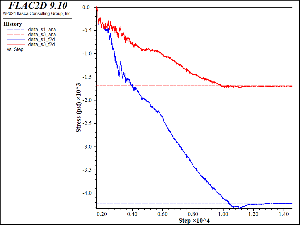
Figure 3: Comparison of change in total principal stresses, \(\Delta \sigma_1\) and \(\Delta \sigma_3\), resulting from the embankment loading.
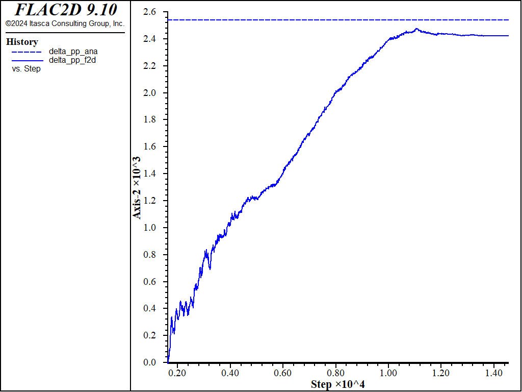
Figure 4: Comparison of change in pore pressure, \(\Delta u\) , resulting from the embankment loading.
References
Lambe, T. W., and R. V. Whitman. \(Soil Mechanics\). New York: Wiley and Sons (1969).
Skempton, A. W. “The Pore-Pressure Coefficients A and B,” \(Géotechnique\), 4, 143-147 (1954).
Data Files
⇐ Unconfined Flow Toward a Riverbank (FLAC2D) | Smooth Circular Footing on an Associated Mohr-Coulomb Material (FLAC3D) ⇒
| Was this helpful? ... | Itasca Software © 2024, Itasca | Updated: Aug 13, 2024 |
