Open Pit Mine with Faults (FLAC3D)
Problem Statement
Note
The project file for this example is available to be viewed/run in FLAC3D.[1] The project’s main data files is shown at the end of this example.
This example demonstrates the use of Zone Joints for modeling faults in a large rock slope. Virtually the same procedures can be used to build the model with interfaces. The advantage of Zone Joints is that they are two-sided, so the order in which they are created does not affect the results, and forces/displacements at the intersections are more accurately calculated. The model is obviously an over-simplified version of a true simulation of open pit mining, but it runs quickly and demonstrates the main considerations for modeling faults in FLAC3D.
Model Geometry
The model is created in Griddle as shown in Tutorial 7 of the Griddle 2.0 manual. A tetrahedral volume mesh is created and exported in FLAC3D binary format. The grid file is included with this example. Note, it is recommended that in general, a hexahedral-dominant mesh be used in FLAC3D, but the Griddle example shows the creation of a tetrahedral mesh, so that is what is used in this example. The following procedures would not be different for a hex-dominant mesh.
The imported model is shown in Figure 1 and Figure 2. Some of the faces represent faults, and others simply stratigraphic boundaries. In the following sub-sections we will show how to use the faces to create faults and define stratigraphic layers.
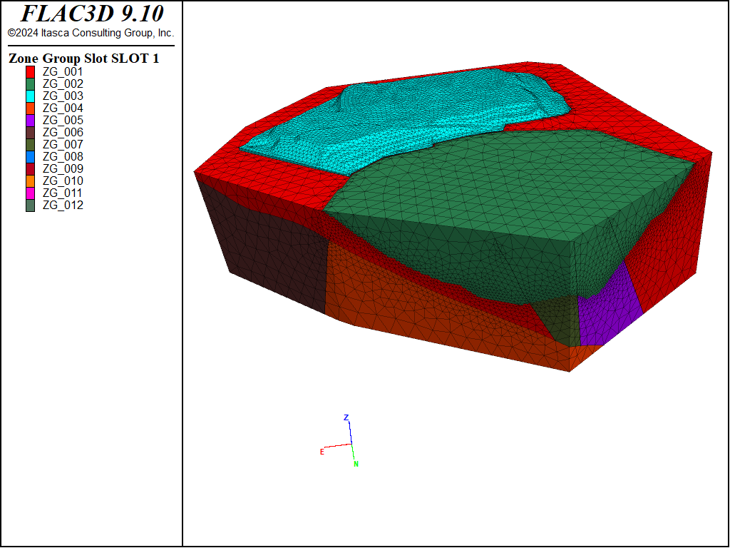
Figure 1: Model imported from Griddle showing zone groups.
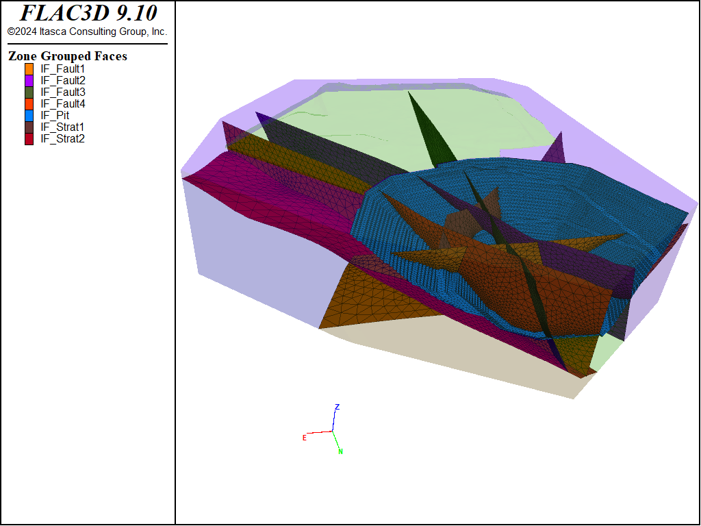
Figure 2: Face groups imported from Griddle. Outer faces are hidden to show inside of the model.
Faults
Faults are now created by separating the fault faces such that gridpoints and faces are duplicated, which will allow sliding and separation on the faults. Creating the faults is a two-step process. First the faces and separated and then the contacts are recognized. The necessary commands are shown below.
; Group all faults for zone joints in the same slot.
zone face group 'Fault1' slot 'joint' internal range group 'IF_Fault1'
zone face group 'Fault2' slot 'joint' internal range group 'IF_Fault2'
zone face group 'Fault3' slot 'joint' internal range group 'IF_Fault3'
zone face group 'Fault4' slot 'joint' internal range group 'IF_Fault4'

; ------ create zone joints -------
; This will do the separation efficiently, removing attaches, and also
; create the zone joints.
zone joint configure
zone joint create by-slot 'joint' separate
Note that the command zone joint configure is required before zone joints can be created. This automatically sets the analyses to be small strain (large strain is not yet supported for zone joints). This also automatically assigned a Mohr-Coulomb contact model to any subsequently created contacts.
Models coming from Griddle often contain imperfectly aligned faces. It may be necessary to increase tolerances used when identifying contacts. See the documentation for zone joint create command under the create-contacts keyword for details.
Geology
In reality, the volume being modeled will contain many different geological units. In this example, we will assume only two units, plus a waste dump. To identify zones belonging to the different units, we can use the group names automatically assigned by Griddle and just give them more representative names.
Similarly the zones making up the region to be excavated can also be identified. Note that a different slot is used when assigning the pit group names so that these zones have two names (a geological name and an excavation name).
The resulting units are shown in Figure 3
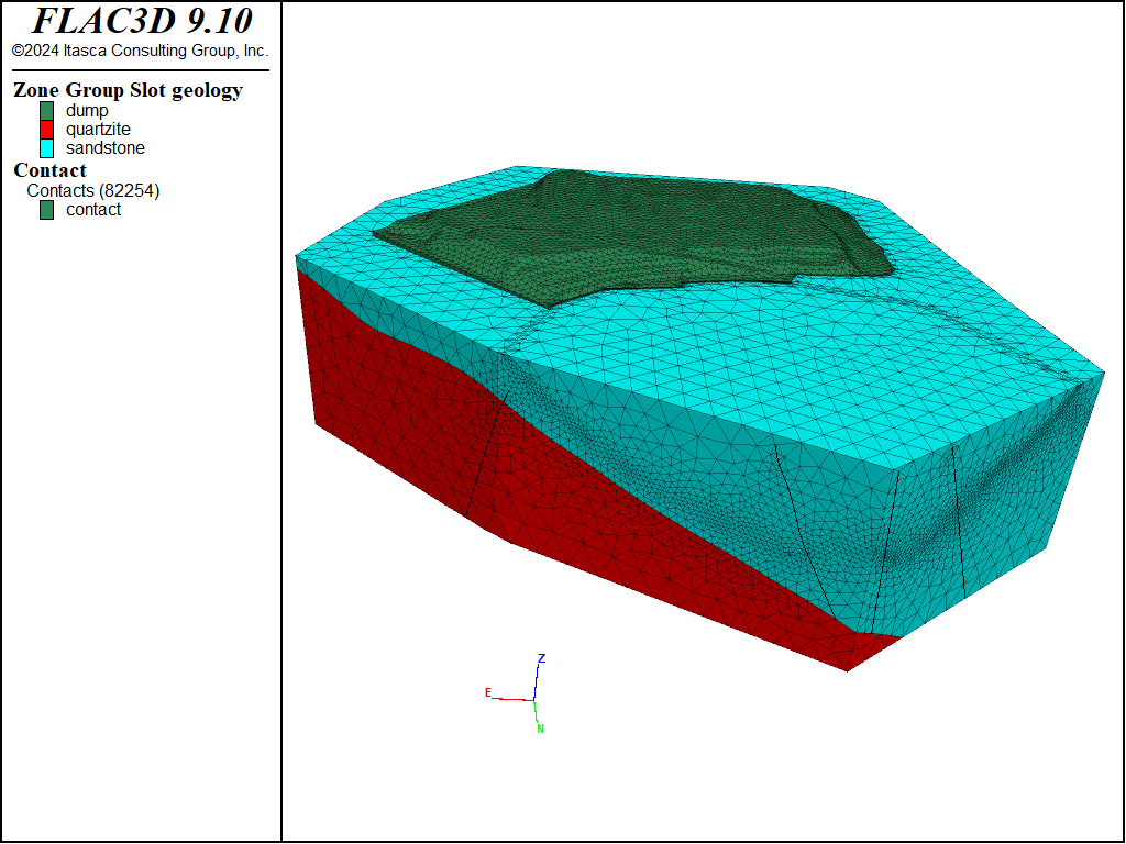
Figure 3: Geological units in the model.
Properties
The sandstone and quartzite are assigned a Hoek-Brown constitutive model with the properties as shown in the data files. The waste dump is likely unconsolidated, weak material. Since the geometry of the dump is not totally realistic (the sides are vertical) and we really only care about the effect of its weight on the pit stability, it is set to be elastic.
The faults are assigned a cohesion of 50 kPa and a friction of 30 degrees, except for the main fault that cuts through the pit, which is assumed to be weaker with a friction of 20 degrees (Figure 4)
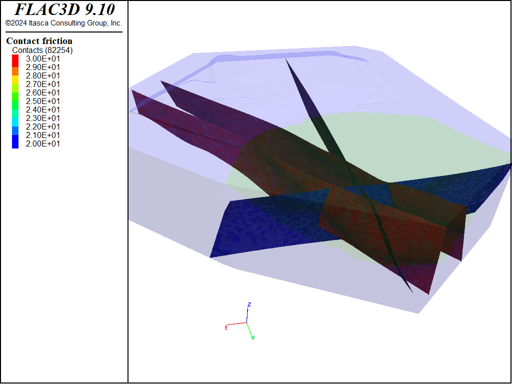
Figure 4: Fault friction angle.
Initial State
Roller boundaries are assigned to the side boundaries and the bottom of the model is fixed. It is assumed that the horizontal stresses are equal to the vertical stresses (initially). Note that stress are set in the zone joints after stresses are set up in the zones, using the command:
; set initial zone stresses
The same approach is used if using interfaces rather than zone joints.
Finally, the model is solved and the initial stress state is determined, as shown in Figure 5 and Figure 6
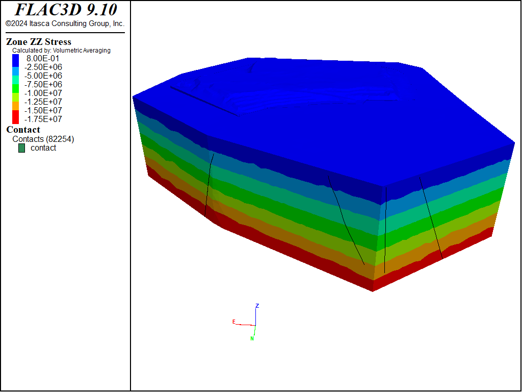
Figure 5: Initial vertical stress in the model
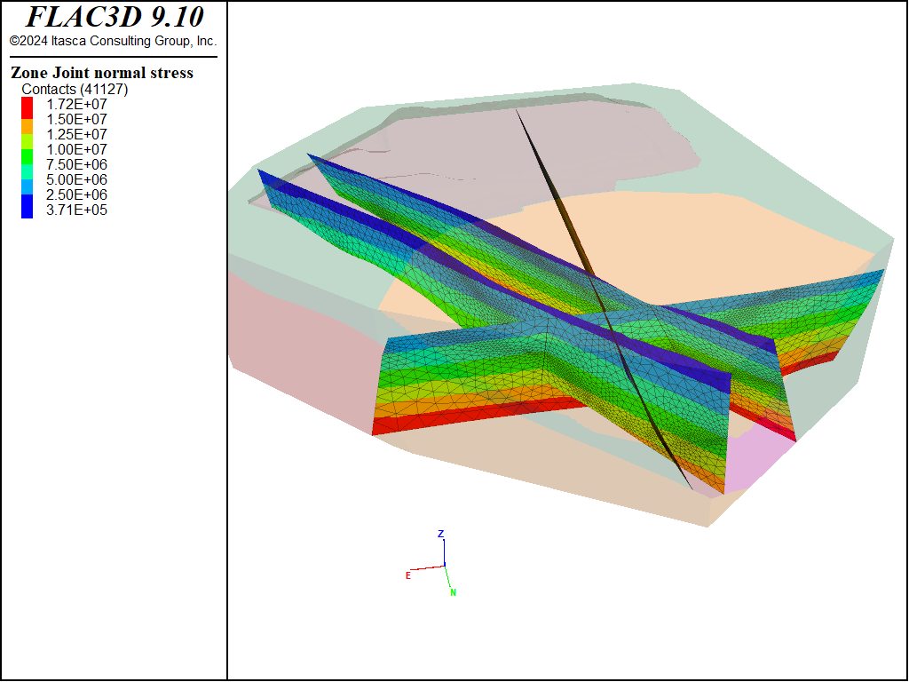
Figure 6: Initial normal stress on the faults.
Excavation
After reaching the initial state, the displacement are reset to 0, and the pit is gradually excavated using the zone relax command. In reality, the pit would be excavated in multiple stages, but for simplicity, it is excavated all at once in this example.
A history of displacement at a point on the crest of the pit is recorded.
The resulting zone and fault displacements are shown in Figure 7 and Figure 8. The recorded history is displayed in Figure 9 and the slip state of the faults is shown in Figure 10. It is clear that the weak fault results in a large amount of displacement in the pit wall.
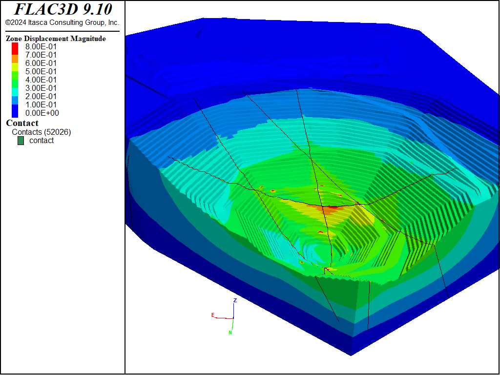
Figure 7: Displacements in the model after excavation.
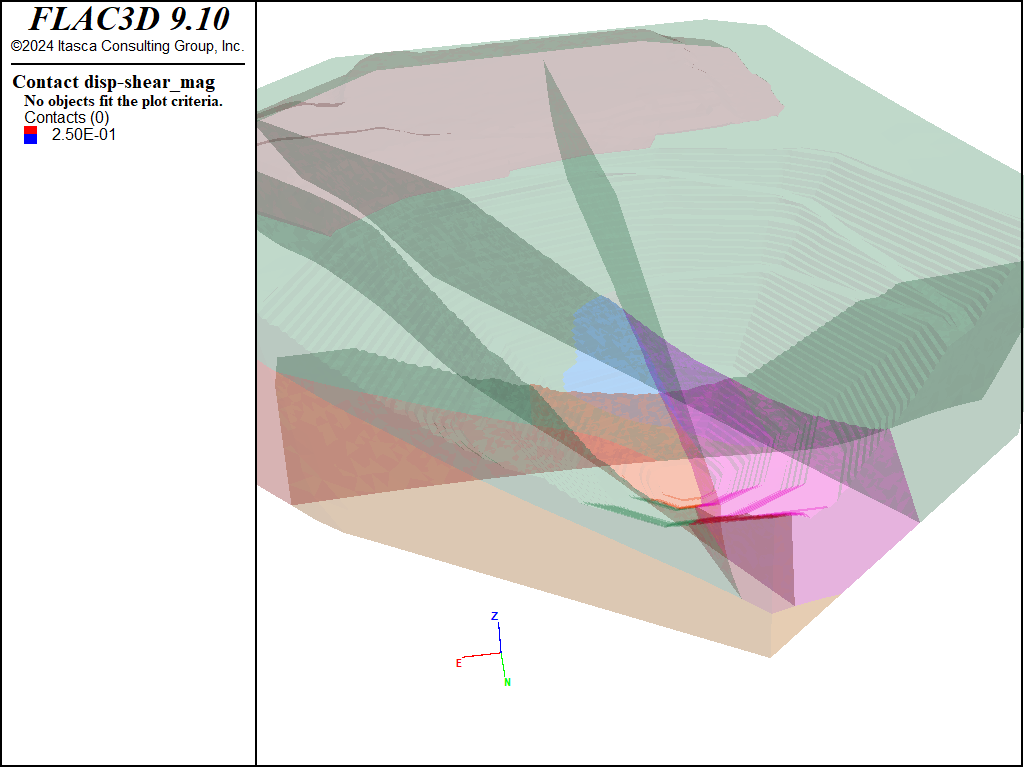
Figure 8: Displacements in the faults after excavation.
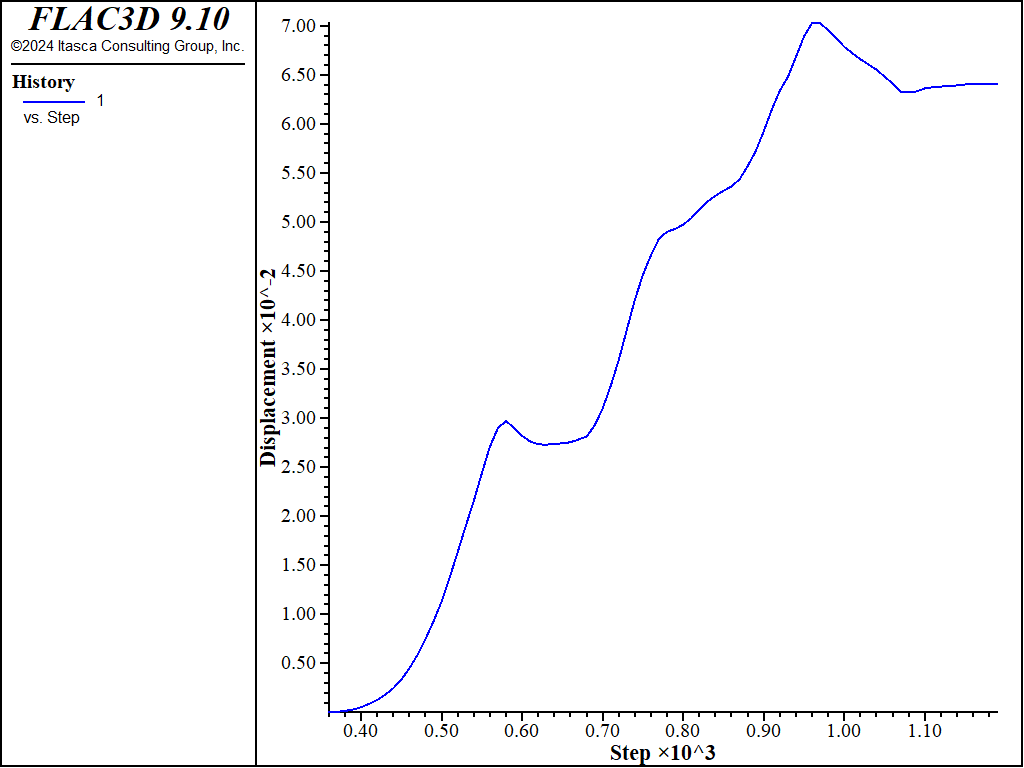
Figure 9: History of displacement at a point on the crest of the pit.
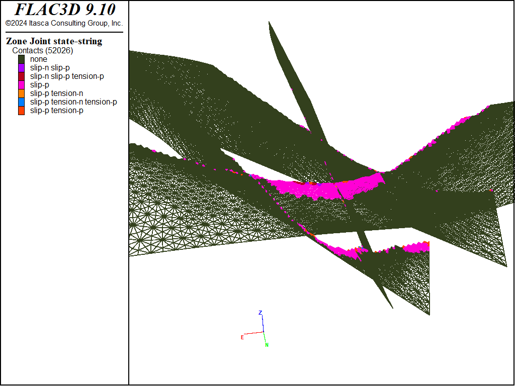
Figure 10: Slip state of the faults after excavation.
Data Files
initial.dat
model new

zone import "T7_LargeOpenPitModel_final_GVol_Binary.f3grid"

; identify boundaries for applying BCs later
zone face skin

; Group all faults for zone joints in the same slot.
zone face group 'Fault1' slot 'joint' internal range group 'IF_Fault1'
zone face group 'Fault2' slot 'joint' internal range group 'IF_Fault2'
zone face group 'Fault3' slot 'joint' internal range group 'IF_Fault3'
zone face group 'Fault4' slot 'joint' internal range group 'IF_Fault4'

; ------ create zone joints -------
; This will do the separation efficiently, removing attaches, and also
; create the zone joints.
zone joint configure
zone joint create by-slot 'joint' separate

; ----- identify layers -------
zone group 'sandstone' slot 'geology'

; quartzite below the stratigraphic boundary
zone group 'quartzite' slot 'geology' range group 'ZG_004' or 'ZG_006'

; dump
zone group 'dump' slot 'geology' range group 'ZG_003'

; pit in a different group slot
zone group 'pit' slot 'excavation' range group 'ZG_002'

; ---------------- zone properties (Pa) ------------------
zone cmodel assign hoek-brown
zone property  density 2800 young 10e9 poisson 0.25 range group 'quartzite'
zone property  constant-sci 70e6 constant-mi 25 geological-strength-index 50 ...
  constant-dilation 9 range group 'quartzite'

zone property  density 2600 young 7e9 poisson 0.25 range group 'sandstone'
zone property  constant-sci 30e6 constant-mi 12 geological-strength-index 36 ...
  constant-dilation 7 range group 'sandstone'

; make the dump elastic.  We only care about its weight
zone cmodel assign elastic range group 'dump'
zone property  density 1900 young 1e8 poisson 0.3 range group 'dump'

; ------------- fault properties ------------------
contact property stiffness-normal 1e8 stiffness-shear 1e8 friction 30 cohesion 50e3

; main fault is weaker
contact property friction 20 range group 'Fault1'

; ---------- Boundary and initial conditions ----------------
model gravity 9.81
zone face apply velocity-normal 0 range group 'West8' or 'East5' ...
    or 'North14' or 'North15'
zone face apply velocity 0 0 0 range group 'Bottom3'

; set initial zone stresses
zone initialize-stresses ratio 1.0

; set zone joint stresses based on zone stresses
zone joint initialize-stresses

;zone nodal-mixed-dis on

model solve elastic

model save 'initial'
excavate.dat
model restore 'initial'

zone gridpoint initialize displacement 0 0 0
zone gridpoint initialize velocity 0 0 0
zone initialize state 0

; take history of point at the edge of the pit
zone history displacement position  2465,-400,-77

zone relax excavate step 500 range group 'pit'

model solve cycles 501 and ratio 1e-5

model save 'excavate'
Endnote
⇐ Sleeved Triaxial Test of a Bonded Material (FLAC3D) | Smooth Circular Footing on an Associated Mohr-Coulomb Material (FLAC2D) ⇒
| Was this helpful? ... | Itasca Software © 2024, Itasca | Updated: Aug 13, 2024 |
