Reinforced Tunnel Excavation
Problem Statement
Note
To view this project in FLAC3D, use the menu command . Choose “ExampleApplications/ReinforcedTunnelExcavation” and select “ReinforcedTunnelExcavation.f3dprj” to load. The project’s main data file is shown at the end of this example.
Full-face excavation with ground reinforcement has become a common technique to build a large tunnel in different soil/rock conditions. Full-face excavation brings many advantages in terms of logistics and production, but it remains a difficult task to assess the performance/effectiveness of the reinforcement and support at the design phase. The face itself behaves as a temporary support for the cavity and the level of confinement provided by reinforcement elements becomes an important variable for the stability and settlement evaluation. The observational method is a crucial aspect of the design because it allows for data collection in real time and optimizing/modifying the excavation/support system. In this particular example, a monitoring section has been installed during the construction of the tunnel, which has provided good quality data for a back analysis. All the original data concerning the geology and geometry has been obtained from the papers by Janin et al. (2012, 2015) using a finite element platform. Cheng and Lucarelli (2016) performed this example again using the Plastic-Hardening model developed in FLAC3D [*].
Borehole investigations show a fairly horizontal stratigraphy with a high degree of alteration of the bedrock. Figure 1 shows the local stratigraphy along with the instrumentation installed in the monitoring section. The averaged soil properties are summarized in Table 1. Any soil parameters not list in the table are the default values.
| Parameter | Unit | Fill | Colluvium | Bedrock |
|---|---|---|---|---|
| depth | m | 0.0-3.5 | 3.5-5.9 | > 5.9 |
| unit weight (\(\rho\)) | kN/m3 | 19.0 | 20.8 | 24.2 |
| (\(E^{ref}_{50}\)) | MPa | 1.6 | 40 | 240 |
| (\(E^{ref}_{oed}\)) | MPa | 1.6 | 40 | 240 |
| (\(E^{ur}_{50}\)) | MPa | 4.8 | 120 | 720 |
| pressure reference (\(p^{ref}\)) | kPa | 100 | 100 | 100 |
| exponent (\(m\)) | 0.5 | 0.5 | 0.5 | |
| friction (\(\phi\)) | degree | 20 | 30 | 25 |
| dilation (\(\psi\)) | degree | 0 | 0 | 0 |
| cohesion (\(C\)) | kPa | 2 | 10 | 40 |
| stress ratio coefficient (\(K_0\)) | 0.5 | 0.5 | 1.0 |
The instrumentation is composed of two inclinometers on both sides of the tunnel, one vertical extensometer on the tunnel axis, and three target prisms. In addition, four radial extensometers, six vibrating wire strain gauges on the steel rib, five pressure cells, and convergence targets were installed from inside the tunnel. This tunnel was excavated using the so-called “ADECO-RS” method (Lunardi 2008). This method emphasizes the significance of controlling the deformation response of the ground in the core ahead of the tunnel face to the tunnel stability and surface settlement.
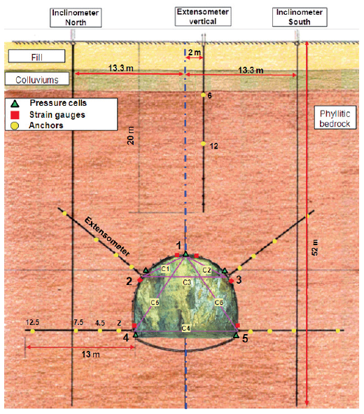
Figure 1: Geological section and instruments (after Janin et al. 2015).
The excavation was progressed by 1.5 m per step and an HEB 180 shotcrete was installed after each excavation step. The tunnel invert was setup using the HEB 220 shotcrete after the excavation face was about 9 excavation steps. Shell elements with a linear elastic behavior are used to model the shotcrete at the tunnel wall, tunnel face and invert. The tunnel wall, face and invert properties are summarized in Table 2.
| Type | Description | Young’s Modulus (GPa) | Thickness (m) |
|---|---|---|---|
| Tunnel wall | HEB 180 | 13.5 | 0.25 |
| Tunnel invert | HEB 220 | 14.0 | 0.30 |
| Tunnel face | 15 cm shotcrete | 10.0 | 0.15 |
Pipe umbrellas (forepole) and horizontal face (fiberglass) bolts were installed. Every 9 m, auto-drilling umbrella pre-support pipes were renewed with a constant inclination of 6 degrees. For face bolts, a constant length of 18 m was installed. The bolt properties are listed in Table 3.
| Forepole Steel Bolts | Fiberglass Bolts | |
|---|---|---|
| Young’s modulus (GPa) | 210 | 40 |
| Cross-section (m2) | 4.88×10⁻⁴ | 8.0×10⁻⁴ |
| Moment of inertia (m4) | 3.27×10⁻⁸ | ~0 |
| Soil/bolt interface resistance (kN/m) | 135 | 135 |
Model Procedure
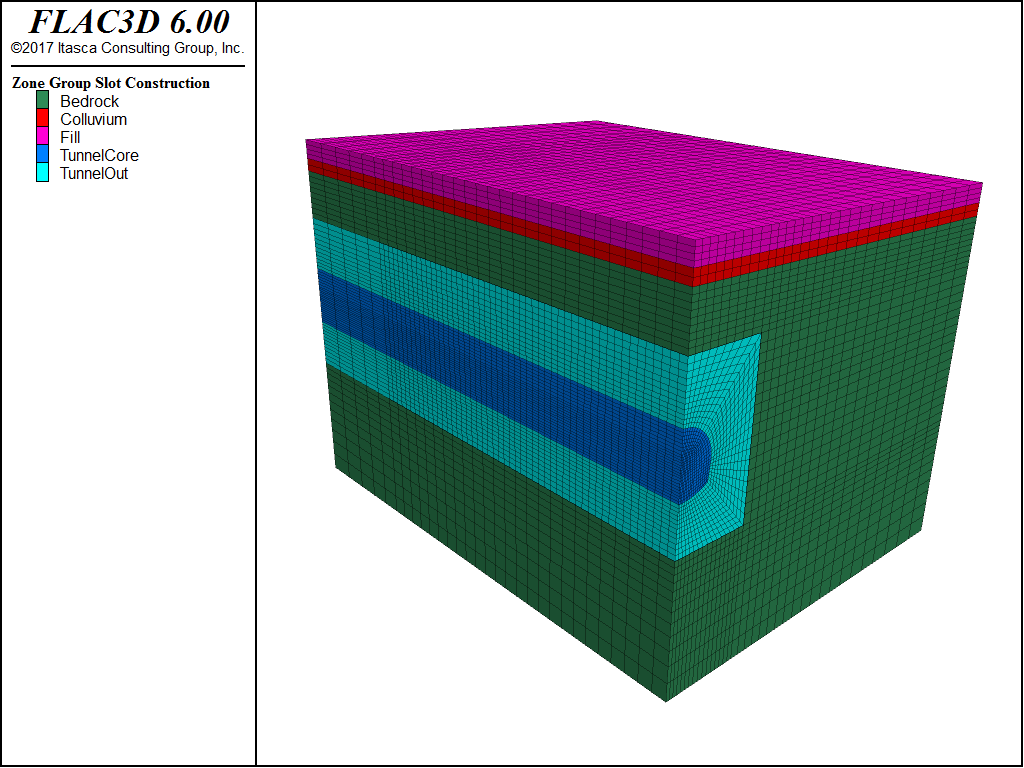
A three-dimensional model has been set up to analyze the tunnel excavation process using
FLAC3D. The model takes advantage of the symmetry of the problem, with the dimension 75 m (half
width) × 70 m (depth). The cross-section of the excavation has an area of about 100 m2
and has been generated using the FLAC3D built-in extruder tool that can generate a 2D mesh and
then extrude it to a 3D mesh. The extension of the model in the transversal direction is of
100 m in order to mitigate boundary effects. The depth of the crown of the tunnel is about 25 m.
The grid has been densified (using the command zone densify) around the region of
interest. Figure 2 shows the geometry of the model.
The in-situ vertical stress is obtained by temporarily setting the soil to be Mohr-Coulomb model
and the command model solve elastic only. The in-situ horizontal stress is then
reset using a FISH function and the \(K_0\) coefficients. With the realistic in-situ
stresses, the soil models are changed into the plastic-hardening models with the properties list
in Table 1.
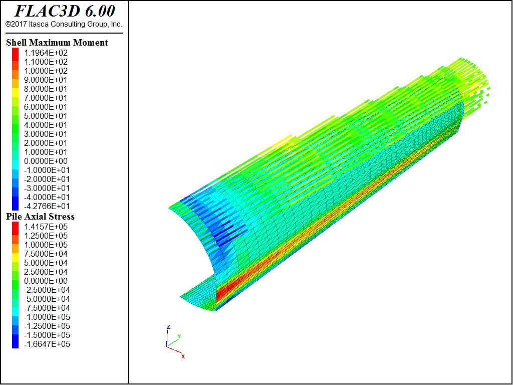
The excavation is carried out in 1.5 m steps. Each step is nulled and so are the structural elements at the face. The face reinforcement (fiberglass elements) and the forepoling are modeled with embedded pile elements and force them to be 18 m. Every 9 m the face reinforcement and roof forepoling are renewed.
The pattern of the face reinforcments and forepoling could have been created once with a CAD program on in the geometry logic, then created with an offset as the tunnel is excavated. In this case, however, we chose to use the FISH functions GenFrontBolt and GenForepole.
After equilibrium is reached, the liner, which is modeled by shell elements, is activated to support the free span. Figure 3 shows the bolts and supports.
The whole process is managed via FISH functions and can easily be parameterized in order to quickly test different hypothesis.
Main Results
The main results in terms of displacements are presented in Figure 4 to Figure 6. Figure 4 presents the simulated longitudinal settlements of a surface line placed directly above the tunnel axis versus the distance to the tunnel excavation face. The settlement is distinct starting from a distance about 30 m ahead of the tunnel face, and then the settlement is accelerated and eventually reaches a value of about 0.20~0.25 m, which is between the upper- and lower-bound measured data. Figure 5 presents the simulated transversal settlements of a surface line placed at y = 8 m and perpendicular to the tunnel axis versus the horizontal distance to the tunnel axis, which also fits well with the measured data. The simulated horizontal displacement at the inclinometer (Figure 6) location (13.3 m to the tunnel’s symmetric plane) successfully captures the measured local ‘belly’ at the tunnel level (depth 25 to 35) and the apparent inclination to the tunnel at the shallow level (depth 0 to 10). In sum, the results are in acceptable agreement with the measurements, and the model is capable of capturing the main features observed in the field.
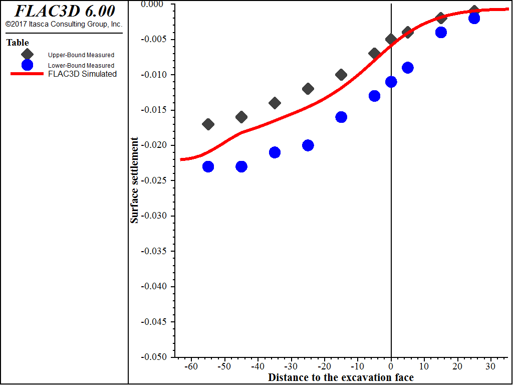
Figure 4: Vertical displacement at ground level along the tunnel axis (dots are upper- and lower-bound measured data, solid line is the simulated result).
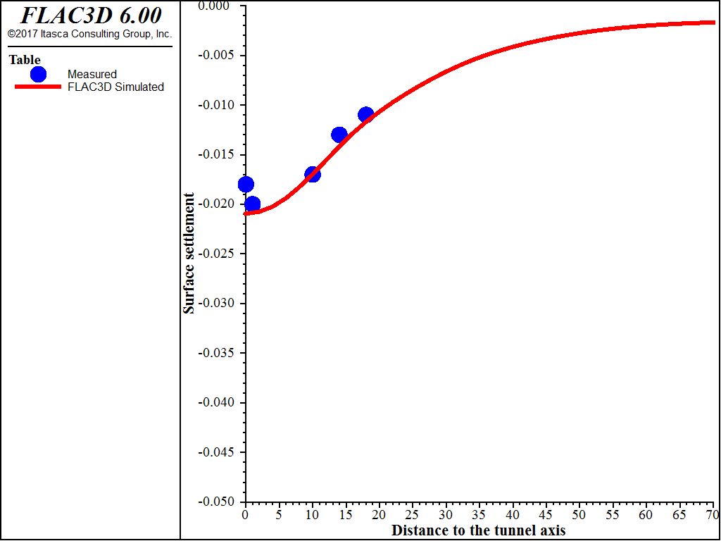
Figure 5: Vertical displacement at ground level in the transversal direction (dots are measured data, solid line is the simulated result).
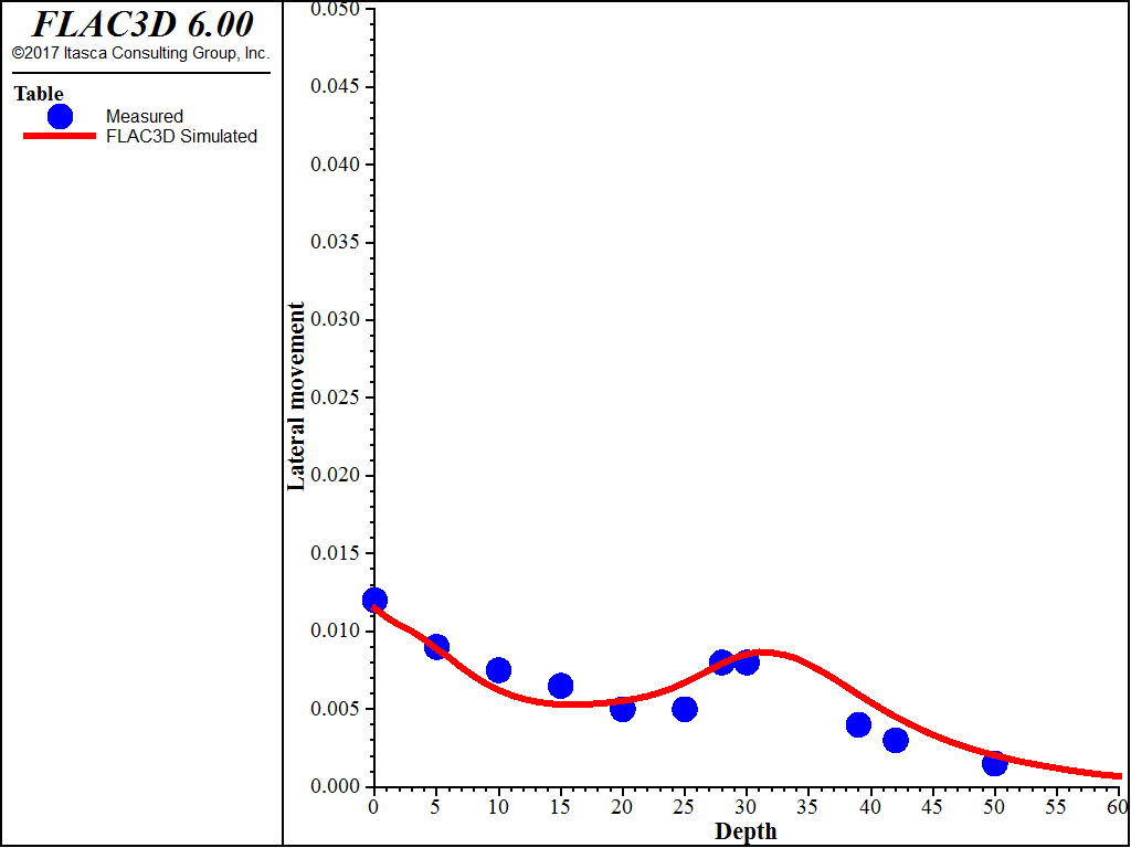
Figure 6: Horizontal displacement at the inclinometer’s position (dots are measured data, solid line is the simulated result).
Endnote
| [*] | This example was adopted from Cheng and Lucarelli (2016), which used a more refined grid. |
References
Cheng, Z., and A. Lucarelli. “Plastic Hardening Model II: Calibration and Validation,” in Applied Numerical Modeling in Geomechanics — 2016 (Proceedings, 4th Itasca Symposium on Applied Numerical Modeling, Lima, March 2016), pp. 393–402, P. Gómez, C. Detournay, R. Hart, and M. Nelson, Eds. Minneapolis: Itasca Consulting Group, Inc. (2016).
Janin, J.P., D. Dias, F. Emeriault, R. Kastner, H. Le Bissonnais, and A. Guilloux. “Numerical back-analysis of the southern Toulon tunnel measurements: A comparison of 3D and 2D approaches”, in Engineering Geology, Issue 195, 42-53. Spring (2015).
Janin, J.P., D. Dias, R. Kastner, F. Emeriault, A. Guilloux, and H. Lebissonnais. “South Toulon tunnel: Analysis of an instrumented section”, In Viggiani, Ed., Geotechnical Aspects of Underground Construction in Soft Ground, London: Taylor & Francis Group. (2012).
Lunardi, P. “Design and construction of tunnel - Analysis of controlled deformation in rocks and soils (ADECO-RS)”, 577, Springer-Verlag, Berlin, Heidelberg. (2008).
Data Files
ReinforcedTunnelExcavation.f3dat
model new
model largestrain off
fish automatic-create off
; grid generation
call 'geometry' suppress ; created using extruder, exported from state pane.
zone generate from-extruder
zone face skin ; Name model boundaries
zone group 'Bedrock' slot 'Material' ...
     range group 'TunnelCore' or 'TunnelOut' or 'Bedrock'
zone densify global seg 1,2,1 range position-y 0 75 group 'TunnelCore'
zone densify global seg 1,2,1 range position-y 0 75 group 'TunnelOut'
zone attach by-face ; Attach boundaries of densified areas
; Assign constitutive model and properties
zone cmodel assign mohr-coulomb
zone prop density 1.90 young 4.8e3 poisson 0.2 friction 20 cohesion  2 ...
     range group 'Fill'
zone prop density 2.08 young 1.2e5 poisson 0.2 friction 30 cohesion 10 ...
     range group 'Colluvium'
zone prop density 2.42 young 7.2e5 poisson 0.2 friction 25 cohesion 40 ...
     range group 'Bedrock'
; Roller boundary conditions
zone face apply velocity-x 0 range group 'East' or 'West'
zone face apply velocity-y 0 range group 'North' or 'South'
zone face apply velocity (0,0,0) range group 'Bottom'
; Initial stress equilibrium
model gravity 10
zone initialize-stresses ratio 0.5 range group 'Fill
zone initialize-stresses ratio 0.5 range group 'Colluvium'
zone initialize-stresses ratio 1.0 range group 'Bedrock'
model solve elastic convergence 10
model save 'ini-stress'
zone initialize state 0
zone gridpoint initialize disp (0 0 0)
;;; change to PH model
zone cmodel assign plastic-hardening
zone prop pressure-reference 100 exponent 0.5
zone prop stiffness-50-reference 1.6e3 stiffness-ur-reference 4.8e3 ...
          friction 20 cohesion  2 range group 'Fill'
zone prop stiffness-50-reference 4.0e4 stiffness-ur-reference 1.2e5 ...
          friction 30 cohesion 10 range group 'Colluvium'
zone prop stiffness-50-reference 2.4e5 stiffness-ur-reference 7.2e5 ...
          friction 25 cohesion 40 range group 'Bedrock'
; Initialize effective stress properties
call 'fishtank' suppress
@iniprin
model solve convergence 10
model save 'ph-soil'
; group slices
zone initialize state 0
zone gridpoint initialize disp (0 0 0)
zone mechanical damping combined
struct damping combined-local
; activate face bolts
@GenFrontBolt(0.75, -26.4, 0, 7, 18.0, 1.5, 12)
@GenFrontBolt(2.25, -27.2, 0, 6, 18.0, 1.5, 12)
@GenFrontBolt(3.75, -27.9, 0, 5, 18.0, 1.5, 12)
@GenFrontBolt(5.25, -30.2, 0, 3, 18.0, 1.5, 12)
; advance the exacavations
fish define excavation
    loop local is (1, 7)
        local yst = (is-1) * 9.0
        ; activate umbrella pre-support
        GenForpole(6.4, 3.0, 0.5, 13, 18.0, yst, 6.0)
        ; advance excavations
        Advance(1+(is-1)*6,is*6,1.5)
    endloop
end
@excavation
fishtank.f3dat
; Initialize stress-effective properties of the plastic-hardening model
fish define iniprin
    loop foreach local z z.list
        local pp   = zone.pp(z)
        if zone.model(z) = 'plastic-hardening' then
            zone.prop(z,'stress-1-effective') = zone.stress.min(z) + pp
            zone.prop(z,'stress-2-effective') = zone.stress.int(z) + pp
            zone.prop(z,'stress-3-effective') = zone.stress.max(z) + pp
        endif
    endloop
end
;
; Generate bolts (using pile elements)
fish define GenFrontBolt(x1,z1,ystart,nb,len,dz,seg)
    loop local ii (1,nb)
        local startp = gp.pos(gp.near(x1,ystart,z1-(ii-1)*dz))
        command
            struct pile create by-ray @startp (0,1,0) @len segment @seg ...
                                      id 1 group 'FiberGlass'
            struct pile property density 0.1 young 4.0e7 poisson 0.2 ...
                    cross-section-area 0.8e-3 moi-y 0.01e-6 moi-z 0.01e-6 ...
                    moi-polar 0.02e-6 coupling-stiffness-normal 1e8 ...
                    coupling-cohesion-normal 1e7 ...
                    coupling-friction-normal 0   ...
                    coupling-stiffness-shear 1e8 ...
                    coupling-cohesion-shear  135 ...
                    coupling-friction-shear  0   ...
                    perimeter 0.20 range id 1
        endcommand
    endloop
end
; Generate forepoling
fish define GenForpole(rads,alst,inter,nb,len,ystart,incl)
    loop local ii (1,nb)
        local svil = rads*(alst*math.degrad) + (ii-1)*inter
        local alfa = svil / rads
        local inclv = math.cos(alfa) * (incl*math.degrad)
        local inclh = math.sin(alfa) * (incl*math.degrad)
        local startp = vector(rads*math.sin(alfa),ystart,-31.4+ ...
                              rads*math.cos(alfa))
        local endp = startp + vector(len*inclh,len,len*inclv)
        command
            struct pile create by-line @startp @endp segment 15 ...
                                       id 2 group 'ForePole'
            struct pile property density 2.4 young 2.1e8 poisson 0.2 ...
                    cross-section-area 0.488e-3 moi-y 0.0327e-6 ...
                    moi-z 0.0327e-6 moi-polar 0.0654e-6 ...
                    coupling-stiffness-normal 1e8 ...
                    coupling-cohesion-normal 1e7  ...
                    coupling-friction-normal 0    ...
                    coupling-stiffness-shear  1e8 ...
                    coupling-cohesion-shear  135  ...
                    coupling-friction-shear  0    ...
                    perimeter 0.10 range id 2
        endcommand
    endloop
end
; Advance a tunnel slice
fish define Advance(slini,slend,Dy)
    loop local ii (slini,slend)
        local tt = ii - 9
        local ysl1 = (ii-1) * Dy
        local ysl2 = ii * Dy
        local ysl3 = ysl1 + 18.0
        command
            ; excavate
            zone cmodel assign null ...
                        range group 'TunnelCore' position-y @ysl1 @ysl2
            ; delete the bolt in the excavation
            struct pile delete ...
                        range group 'FiberGlass' position-y @ysl1 @ysl2
            ; delete the shotcrete on the tunnel face
            struct shell delete range group 'TunnelFace'
            ; activate new tunnel wall
            struct shell create by-face element-type dkt-cst id 1 ...
                         group 'TunnelWall' range group 'TunnelBoundary' ...
                         position-y @ysl1 @ysl2 position-z -35 0
            struct shell property isotropic (13.5e6,0.2) thick 0.25 ...
                                  density 2.4 range group 'TunnelWall'
            ; activate new tunnel face
            struct shell create by-face element-type dkt-cst id 1 ...
                                group 'TunnelFace' ...
                                range group 'TunnelCore' position-y @ysl2
            struct shell property isotropic (10e6,0.2) thick 0.15 ...
                                  density 2.4 range group 'TunnelFace'
        endcommand
        ; extend the fore bolts
        GenFrontBolt(0.75, -26.4, ysl3, 7, 1.5, 1.5, 1)
        GenFrontBolt(2.25, -27.2, ysl3, 6, 1.5, 1.5, 1)
        GenFrontBolt(3.75, -27.9, ysl3, 5, 1.5, 1.5, 1)
        GenFrontBolt(5.25, -30.2, ysl3, 3, 1.5, 1.5, 1)
        ; activate the tunnel invert
        if tt >= 1 then
            command
                struct shell create by-face element-type dkt-cst id 1 ...
                             group 'TunnelInvert' ...
                             range group 'TunnelBoundary' ...
                             position-y [(tt-1)*Dy] [tt*Dy] position-z -70 -35
                struct shell property isotropic (14.0e6,0.2) thick 0.30 ...
                             density 2.4 range group 'TunnelInvert'
            endcommand
        endif
        ;
        command
            ; structure boundary conditions
            struct node fix velocity-x rotation-y rotation-z ...
                   range position-x 0.0 position-z -25.2
            struct node fix velocity-x rotation-y rotation-z ...
                   range position-x 0.0 position-z -36.5
            struct node fix velocity-x                       ...
                   range position-x 0.0
            ; solve
model solve convergence 5
        endcommand

    endloop

    command
        model save ['Excav_slice_' + string(slend)]
    endcommand
end
| Was this helpful? ... | PFC 6.0 © 2019, Itasca | Updated: Nov 19, 2021 |

