
Rigid Block Model of Flying Buttresses
| Example Resources | |
|---|---|
| Data Files | Project: Open “Buttress.prj”[1] in PFC3D |
Problem Statement
The flying buttress is a specific form of buttress composed of an arched structure that extends from the upper portion of a wall to a pier of great mass, in order to convey to the ground the lateral forces that push a wall outward. These forces arise from vaulted ceilings of stone, and from wind-loading on roofs [Curls1999]. The flying buttresses of Notre-Dame Cathedral (Paris, France) and a schematic cross section are shown below. The Notre Dame Cathedral Paris didn’t originally have flying buttresses included in its design. But after the construction of the cathedral began, the thinner walls (popularized in the Gothic style) grew ever higher and stress fractures began to occur as the walls pushed outward. The cathedral’s architects, to fix the problem, built supports around the outside walls. Later additions continued the pattern. The Notre-Dame Cathedral was among the first buildings in the world to use the flying buttress [Notredame].
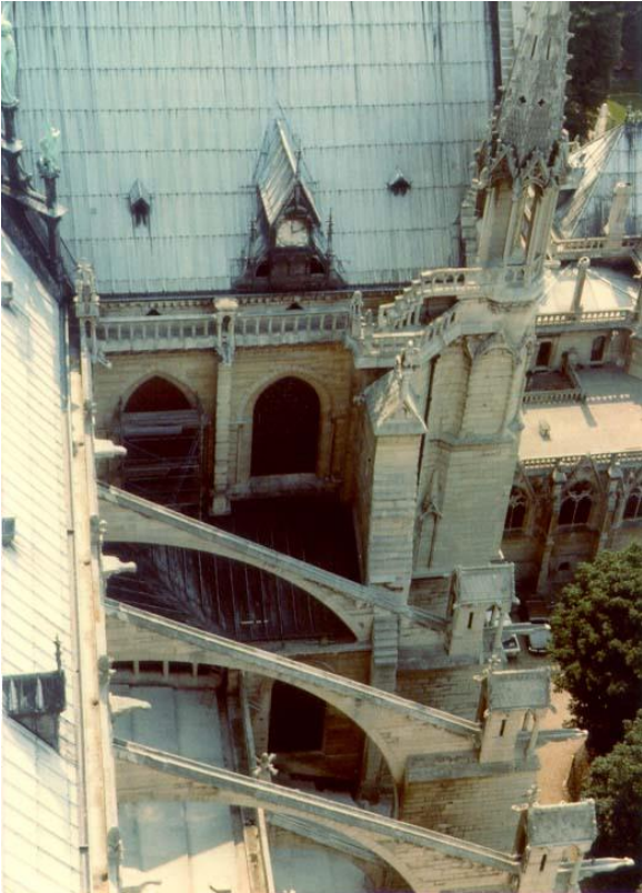
Figure 1: Buttresses of Notre-Dame Cathedral.
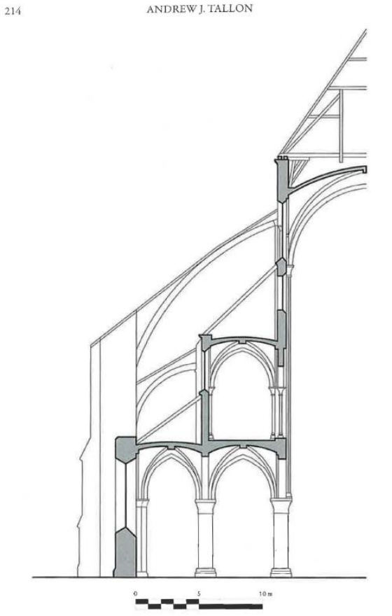
Figure 2: Cross-section of flying buttresses of Notre-Dame Cathedral from [Tallon2011].
This problem analyzed here is an example of a simple buttress with span approximately 11 m and the height is 34 m. The buttresses are modeled as 1 m thick blocks (approximately equal to the true thickness). The Gothic arch at the top represents the continuous vault. As a result, its weight is multiplied by 6 m, the bay spacing, so that the correct outward push is applied to the pillars. The geometry is simplified compared to the true geometry. The figure below shows the rigid block model geometry.
The density of the blocks is set to 2500 kg/m3. As explained above, the density of the arch is set to six times this value (15,000 kg/m3). The friction coefficient is set to 0.7. The contacts that exist between the pillars and the buttresses are bonded, though.
Simulation Results
The model is run with both local and normal viscous damping active. Gravity is turned on and the model with buttresses is solved to the default average ratio of 1e-5. Displacements and contacts are shown below. Note that as a single contact exists between rigid blocks they show clearly the line of action. The same model is then run without buttresses for 2 seconds to show clearly that failure ensues.
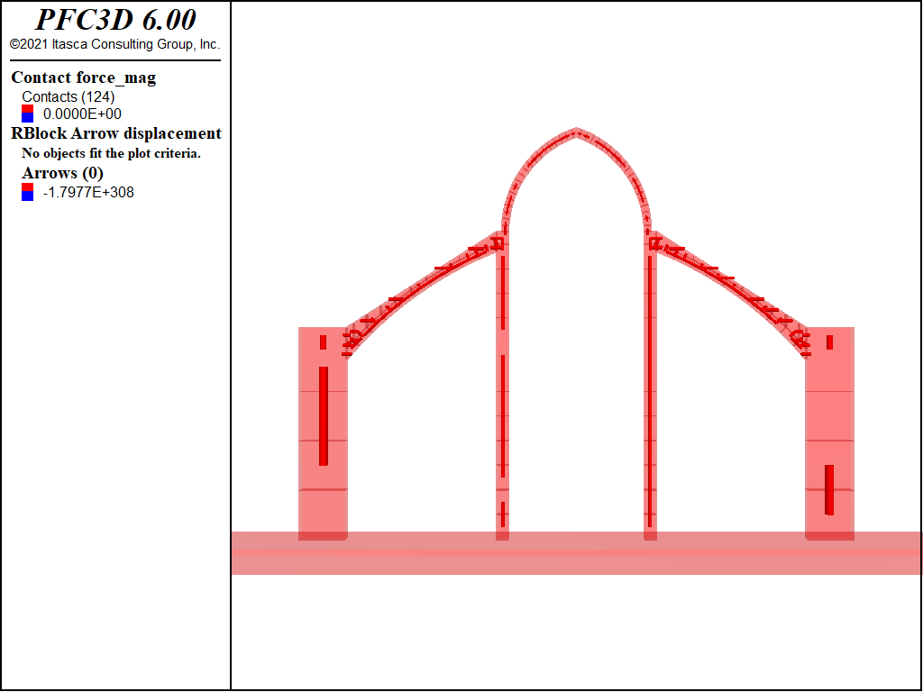
Figure 3: Initial buttress configuration.
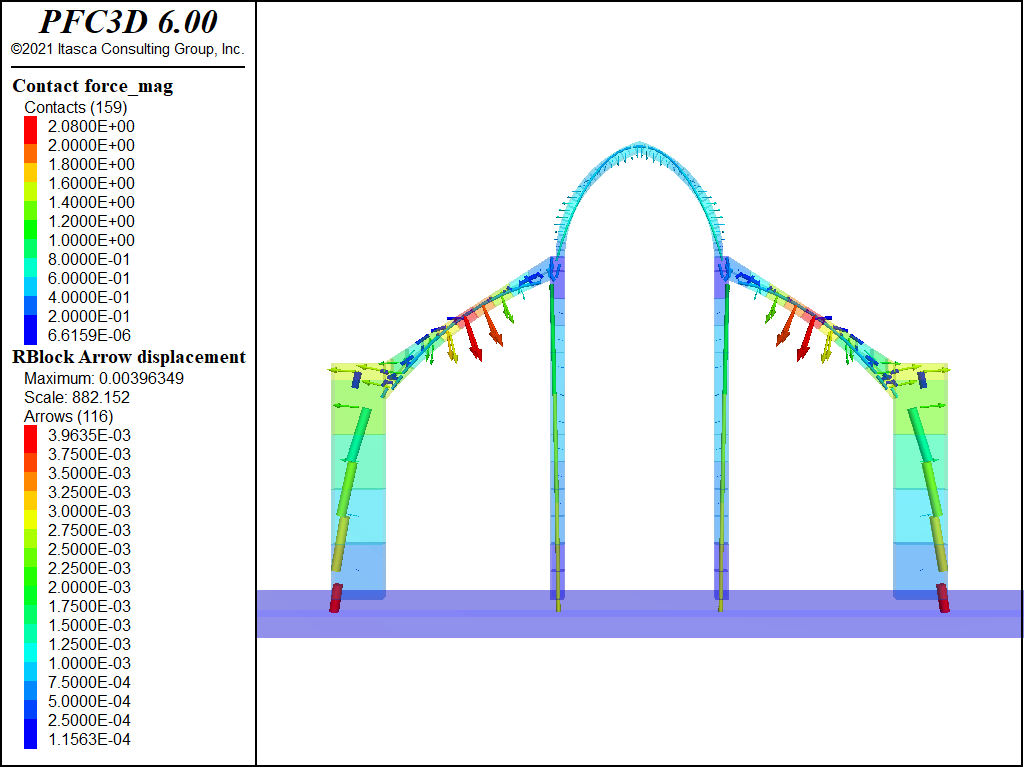
Figure 4: The buttress after settling.
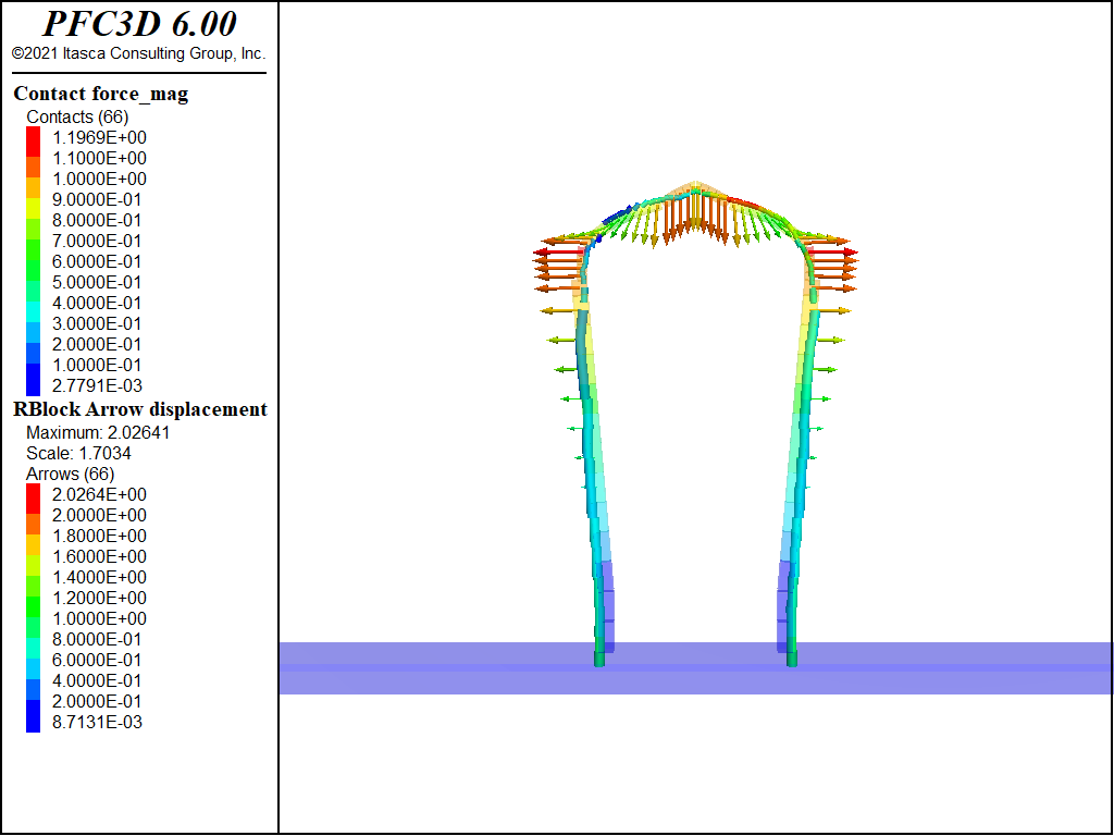
Figure 5: Arch without buttresses after 2 seconds.
References
| [Curls1999] | Curls, J.S. Editor, A Dictionary of Architecture, Oxford, 113-114, 1999. |
| [Notredame] | http://www.notredamecathedralparis.com/ |
| [Tallon2011] | Tallon, A.J., “Rethinking Medieval Structure,” in New Approaches to Medieval Architecture, R. O. Bork, W. W. Clark, A. McGehee (eds.), Routledge, 2011. |
| [1] | These files may be found in PFC3D under the “examples/buttress” folder in the Examples dialog ( on the menu). If this entry does not appear, please copy the application data to a new directory. (Use the menu commands . See the “Copy Application Data” section for details.) |
| Was this helpful? ... | PFC 6.0 © 2019, Itasca | Updated: Nov 19, 2021 |