
Clumps in a Box
| Tutorial Resources | |
|---|---|
| Data File | Project: Open “Clumps in a Box.p3prj” in PFC3D [1] |
Introduction
This simple example is similar to the balls in a box tutorial,
in that objects are placed in a box and allowed to settle. In this case, though, three clump
templates are created to demonstrate the clump template logic (see the clump template
command). This example also demonstrates usage of the clump generate, clump attribute,
and contact cmat default commands, and makes use of the linear contact model.
Numerical Model
The complete data file (3D) for this example is “clumps_in_a_box.p3dat”. Select lines of this file are discussed below, where substantially different from the “Balls in a Box” tutorial. Please review that tutorial for a more thorough description of the domain and Contact Model Assignment Table (CMAT).
As in the ball tutorial, the contact cmat default command is used to select the default mechanical
contact model. The linear contact model is also
selected but, unlike the previous tutorial, additional contact model properties are specified. In
this case, the shear stiffness, normal viscous damping ratio, and friction are specified.
These additional contact model properties allow for energy dissipation without the use
of local damping.
contact cmat default model linear property kn 1.0e6         ...
            ks 5.0e5 dp_nratio 0.5 fric 0.3
The clump template logic is used to create clump objects that can be output as files for
subsequent usage (see the clump template export and clump template import
commands). A clump template is not a model object in itself; it serves as a basis for
creating clumps in the model with the same shape as the clump template. The facilities to
create clumps from clump templates include the ability to rotate, translate, and scale the
clumps relative to their template. One can simply replicate a clump from a template
(see the clump replicate command) or create distributions of clumps
(via the clump generate and clump distribute commands, as discussed below).
The first clump template created (see the clump template create command)
in this tutorial consists of a single pebble. The full inertia tensor and volume
of the clump template are specified explicitly. The number of pebbles,
their radii, and locations are also specified. Note that one could set the inertial
attributes arbitrarily.
[rad = 0.5]
[vc   = (4.0/3.0)*math.pi*(rad)^3]
[moic = (2.0/5.0) * vc * rad^2]
clump template create name 'single'                 ...
            pebbles 1                               ...
            @rad 0 0 0                              ...
            volume @vc                              ...
            inertia @moic @moic @moic 0 0 0
The second clump template uses a different approach to calculate the inertial attributes.
In this case, the clump consists of two overlapping pebbles with the same radii. One can
analytically calculate the volume and inertia tensor of this configuration, or use the
pebcalculate keyword to calculate these parameters from the
pebble configuration. A voxelization approach is used: it recursively subdivides the
volume occupied by the pebbles into {squares in 2D; cubes in 3D} to estimate the inertial
attributes to a specified tolerance.
clump template create name 'dyad'                   ...
            pebbles 2                               ...
            @rad [-rad*0.5] 0 0                     ...
            @rad [rad*0.5] 0 0                      ...
            pebcalculate 0.005
The third clump template uses yet another approach to specify both the pebbles and the inertial attributes. This clump template is based on an .stl surface description of a dolos as shown below. Dolosse are used to protect coastal areas from erosion due to wave action.
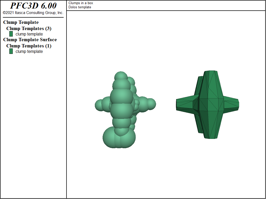
Figure 1: The dolos surface description (right) and resulting pebble distribution (left) from the BubblePack algorithm.
It may be rather difficult to manually specify the inertial attributes and pebble locations
of a clump template representing this geometry. Instead, the triangulated, closed, and manifold
surface description of the dolos is imported as a geometry set (see the geometry import
command), and this geometry set is used to calculate the inertial properties of this shape
using the surfcalculate keyword. The pebbles are automatically
calculated via an approximation of the medial surface of the dolos using the
bubblepack algorithm. Both convex and concave geometries can
be automatically filled via this algorithm in both 2D and 3D.
The ratio keyword specifies the
ratio of the smallest to largest pebble in the clump template, while the distance
keyword specifies an angular measure of the smoothness of the pebble distribution. In this way,
one can control the fidelity with which the pebble distribution matches the surface representation.
The surface is not used to resolve contacts; the pebbles alone are used for this purpose.
The surface description is a tool that can be used to define the pebble radii/locations and the
inertial attributes. An additional benefit of providing a surface description is that clumps may be
visualized by this surface description, as shown below.
geometry import 'dolos.stl'
clump template create name 'dolos'                  ...
            geometry 'dolos'                        ...
            bubblepack ratio 0.3 distance 120       ...
            surfcalculate
Subsequent to the generation of the material vessel in which clumps will settle, the clumps are
generated with the clump generate command. This command places clumps in a box without
overlap. The first set of generated clumps have random orientations and volumes equivalent to
a sphere with diameter 1.5. The volume and inertia tensors are scaled automatically. In this case,
all clump templates are sampled equally to generate 50 clumps. The group specifier bottom is
set for these 50 clumps.
clump generate diameter size 1.5 number 50          ...
            box -5.0 5.0 -5.0 5.0 -5.0 0.0          ...
            group 'bottom'
One may wish to control both the proportion of clumps based on specified templates and their
orientations relative to the template orientations. The code below accomplishes both of
these goals via the templates, azimuth, elevation, and tilt
keywords. Notice that multiple clump generate commands can be given with the same
spatial box, and that the clumps generated from these separate operations do not overlap.
As with balls, an additional command exists (clump distribute) to create a
set of clumps meeting a target porosity where overlaps are allowed. This logic works similarly
for balls and clumps. See the “Replicating a Particle Size Distribution” tutorial
for a simple example.
clump generate diameter size 1.5 number 25          ...
            box -5.0 5.0 -5.0 5.0 0.0 5.0           ...
            templates 2                             ...
            'dyad' 0.3 'dolos' 0.7                  ...
            azimuth 45.0 45.0                       ...
            tilt 90.0 90.0                          ...
            elevation 45.0 45.0                     ...
            group 'top1'

clump generate diameter size 1.5 number 25          ...
            box -5.0 5.0 -5.0 5.0 0.0 5.0           ...
            templates 2                             ...
            'dyad' 0.7 'dolos' 0.3                  ...
            azimuth -45.0 -45.0                     ...
            tilt 90.0 90.0                          ...
            elevation 45.0 45.0                     ...
            group 'top2'
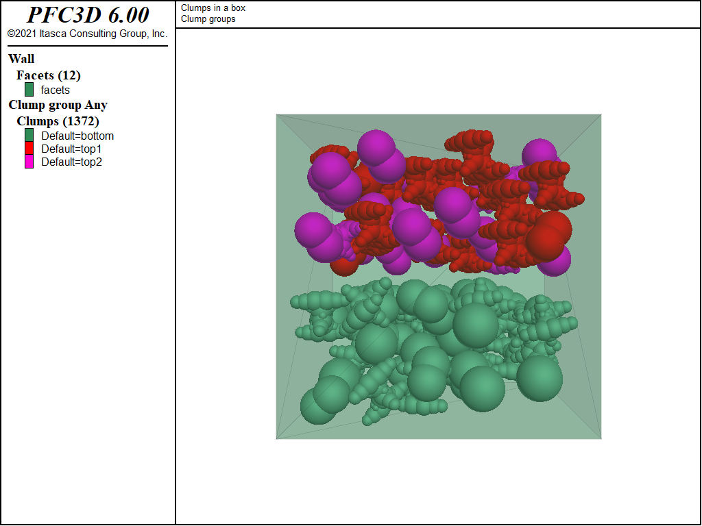
Figure 2: Clumps colored by their group identifiers. The groups correspond to different instances of
the clump generate command and do not overlap.
The clumps are then allowed to settle in the box under gravity. At an intermediate stage of settling, one can see that many of the clumps near the top of the model are moving uniformly under gravity. These clumps did not overlap at generation and continue to fall adjacent to one another with the same velocity. The clumps quickly reach equilibrium in the box.
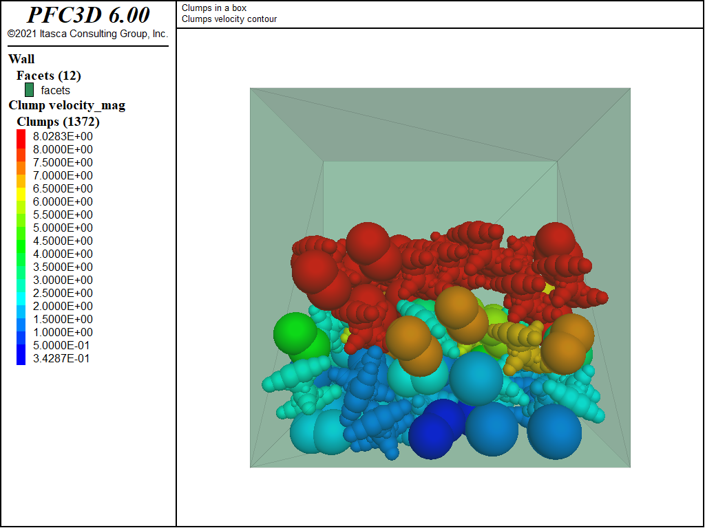
Figure 3: Clumps colored by velocity after 0.8 time units.
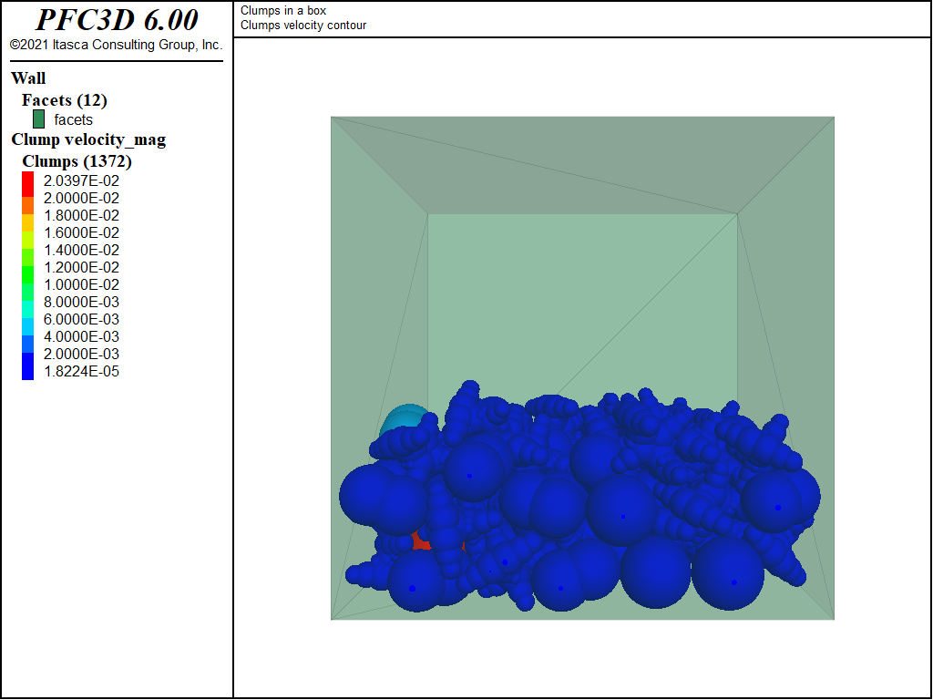
Figure 4: Clumps colored by velocity after solving to equilibrium.
Discussion
This example introduces the clump template logic and the main steps to build a simple PFC model out of clumps. Philosophical questions arise from this capability: What does a clump represent? Should a clump have the inertial attributes of a surface defining its geometry? Should the clump inertial attributes correspond to the actual pebble attributes used for contact resolution? This logic allow for both approaches.
Endnote
| [1] | This may be found in PFC3D under the “tutorials/clumps_in_a_box” folder in the Examples dialog ( on the menu). If this entry does not appear, please copy the application data to a new directory. (Use the menu commands . See the -ref–dlg_copyappdata- section for details. [CS: commented out because UI material not present as of 9/25/17, therefore link is broken. Put back in when UI material is restored]). |
| Was this helpful? ... | PFC 6.0 © 2019, Itasca | Updated: Nov 19, 2021 |